
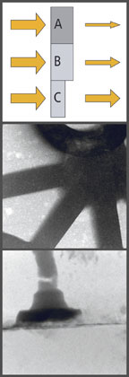
Middle: Microfocus X-ray image of an aluminum casting at three-fold magnification. The contrast is because of varying thickness. Note the porosities on the sample,
Bottom: Nanofocus X-ray image of a gold bond wire that is visible in the thick package because of its high density. The crack is 2 microns in width, but it images clearly at about 1,000 times magnification. Photo: phoenix|X-ray Systems + Services Inc.
Conventional film-less X-ray inspection technologies provide 2-D transmission X-ray images. An X-ray shadow reflects the density and thickness of a sample that is then projected onto a detector, and a viewable image is produced on a display monitor. High-density sections of a given sample will absorb more X-ray energy than lower density areas, providing an image with different brightness levels that directly correspond to the shape and density of the sample. Features of interest within a sample that are in front of or behind one another are imaged in exactly that orientation. As a result, specific areas of interest can be “blocked-out“ by higher density features within the sample.
For many applications, such as casting inspections, printed circuit board (PCB) assemblies, weld seams, some electro-mechanical assemblies and various sensor types, two dimensional X-ray images are adequate for the standard quality-inspection requirements. However, because of the nature of 2-D X-ray images, depth of detail is not quantifiable, which in some cases can be vital to the manufacturing process. Microfocus computed tomography (CT) presents an effective method of mapping the internal structure of components in three dimensions.
Conventional X-Ray imaging
The image produced with a conventional X-ray imaging system can range anywhere from a 1X magnification ratio to more than 1,000 times magnification with an advanced technology microfocus X-ray source. Fine feature recognition is achieved at these high magnification levels, but there is an inherent limitation. While measurement accuracy can be high in the vertical and horizontal planes of the image, which represent the height and width of the sample, the depth of the sample is only measurable in terms of grey-scale intensity or density values. In other words, it is possible to image a defect in a sample such as a void in a casting or a crack in a weld and measure the height and width accurately, but there is no effective way to measure the depth of such a defect with a conventional 2-D image.In some instances, a sample could be salvaged if the defect can be accurately located within the depth of the sample for removal or repair. In other situations, changes can be made to the manufacturing process that will correct the problem for the production line. Achieving depth recognition in situ with height and width recognition is only possible by 3-D imaging. In fact, an increasing number of situations require 3-D sample information to make an accurate determination about the status of a sample or an indication within. For example, in the case of an electrical assembly where a wire crimp is failing or in a complex fuel injector nozzle where a mechanical failure is occurring, 3-D information can identify the problem area to be corrected. This problem is not otherwise detectable when imaging the sample in a conventional 2-D X-ray process that images the sample through its entire depth.
For these challenging X-ray inspection applications, using microfocus computed tomography can obtain the needed results. Microfocus-CT uses a stable microfocus X-ray tube as the X-ray source and is one of the most sensitive CT solutions producing ultra-high resolution results. The microfocus X-ray source enables detectability of features with sizes down to the 4-micron range, which are otherwise not easily detected with most other non-destructive X-ray methods.
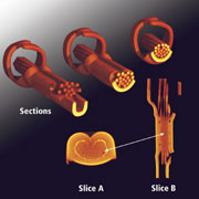
Microfocus-CT with volumetric capabilities can non-destructively visualize samples in three dimensions, facilitating the reverse-engineering process. In doing so, productivity can be improved by reducing development costs, improving safety factors and increasing yields. Additionally, non-destructive slicing and sectional viewing of samples are incorporated into microfocus-CT to facilitate this process as well.
How it works
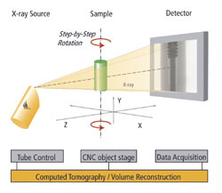
Generating 3-D images using microfocus-CT starts with the acquisition of a series of 2-D X-ray images. The series of two dimensional X-ray projections is a collection of images acquired while progressively rotating the sample step-by-step through a full 360-degree rotation within the field of view at increments of less than 1 degree per step. These projections contain information on the position and density of absorbing object features within the sample. This accumulation of data is then used for the numerical reconstruction of the volumetric data. This volume data is compiled as a visualization of the reconstructed layers in a 3-D view.In order to reproduce an accurate reconstruction of the volumetric data, two conditions must be met. First, the entire sample depth and diameter throughout the entire 360-degree rotation must remain within the field of view and cone of radiation so that the full-sample diameter is completely displayed in each projection captured in the acquisition process.
Second, the entire geometry of the sample, meaning every acquisition angle throughout the full 360-degree rotation, must be fully penetrated and imaged at the energy level with which the sample is scanned. This can be accomplished successfully even for higher density samples with a high power X-ray source and correctly preparing the X-ray beam by filtering out long wavelength X-rays.
Applications
In general, any sample that can fit entirely within the field of view at a given level of magnification and can be completely penetrated through all directions perpendicular to the rotational axis, can be imaged using the Micro-CT technique.In various industries, many potential samples meet the above conditions whereas the achievable resolution is only limited by the achievable magnification. The resolution is equal to the minimum achievable voxel size. Geometric magnification is the most significant advantage that microfocus-CT offers over conventional CT.
Typical applications for microfocus-CT, include:
• Automotive: Sensors, glow plugs, tubes, valves, injector nozzles, switches, relays, seals, crimps, connectors and smaller castings.
• Electronics: Compact devices such as mobile phone mechanics, MEMS, laser diodes, light sources, satellite batteries and barium tantalite capacitors.
• Mechanics: Medical devices such as artificial joints, micromechanical devices, inkjet cartridges and endoscopes.
• New materials: Metal foams, cera-mics, fiber composite materials and parts, conglomerates and sintered alloys.

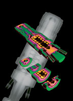
An axial section of the crimp shows that 19 strands go in, but only 17 go out. The section parallel to the axis reveals a tiny channel starting approximately from the middle of the crimped area. In the corresponding axial section, a small hole is detected that indicates the position where the two missing strands end.
This example shows that not only do the 3-D sections enable the detection and clear visualization of areas that are otherwise concealed in conventional 2-D radiographic images, but moreover, they provide better contrast. With conventional 2-D radiographic images, it is not possible to display the channel in the crimp because of a lack of contrast, even with the use of a superior digital detector. Yet, the superposition of the 500 projections in the tomographic image did yield a sufficient contrast.
With a cycle time of about 10 to 15 minutes, including acquisition and reconstruction, microfocus-CT can compete with the only other alternative able to show the described defects, which would be destructively slicing the sample. Furthermore, whereas, the destructive act of slicing can display a sample section in only one direction and position, microfocus-CT sections can be applied to the sample at any position and in any orientation. Even if the defects considered were visible in a two-dimensional image, 10 minutes are spent by inspecting the sample from various angles.
Timely images
Microfocus-CT provides high resolution, 3-D images that can only be achieved using the high geometric magnification capabilities of a true microfocus X-ray source. In addition, highly accurate 3-D measurements can be taken to facilitate the reverse-engineering process.In practice, this means that microfocus-CT expands the spectrum of X-ray detectable defects in process control and failure analysis thereby increasing reliability and safety of components for automotive, aerospace and military applications. Similar to CT in medical diagnostics in the last decade, microfocus-CT currently is in the process of becoming a state-of-the-art method of inindustrial quality control and its application during design and production may be considered in product liability issues.
In addition, microfocus-CT can at least partially substitute destructive methods and thus save costs and time. All these capabilities contribute to an early detection of process and product weaknesses, increasing yield and
productivity.
TECH TIPS
• Microfocus computed tomography presents an effective method of mapping the internal structure of components in three dimensions.• Situations where 3-D sample information is a prerequisite to making an accurate determination about the status of a sample.
• Non-destructive slicing and sectional viewing of samples are valuable features incorporated into microfocus-CT.
• Geometric magnification is the most significant advantage that microfocus-CT offers compared to conventional computed tomography.
• Accurate 3-D measurements can be accomplished to facilitate the reverse-engineering process.
Formula to determine achievable resolution
Vmin = P / MmaxWhere: V = voxel; P = pixel size; M = magnification (Detector width / Sample Diameter)
