Quality Magazine
  Home
  Subscribe
  Subscribe to eNewsletter
  Subscription Customer Service
  Online
  Industry Headlines
  Web Exclusives
  Blogs
  Quality Product Spotlights
  White Papers on the Web
  Quality Downloads
  Webinars
  Quality Showcases
  e-Inserts Plus
  Online Store
  More Product Info
  Archive
  Q-Tube
  Q-Cast Podcasts
  Quality Showrooms
  Current Issue
  Coming Events
  Features
  Departments
  Columns
  Brain Teasers
  Products
  Quality Quick Clicks
  Special Sections
  NDT
  Vision & Sensors
  Aerospace
  How To Guide
  Global Editions
  China Editions
  Quality Guides
  Quality Buyers Guide
  Software Selector
  Registrars Guide
  Services Guide
  Quality Services
  Job Marketplace
  Industry Links
  Classifieds
  Career Center
  Events
  2009 Quality Conferences
  Quality Expo Detroit
  IMTS
  Meetings and Shows
  Industry Webinars
  Quality Awards
  2009 Quality Plant of the Year
  2009 Quality Professional of the Year
  Quality Leadership 100
  Quality Info
Search in: EditorialProductsCompanies
Quality 101: Defining GD&T
by Don Day
June 29, 2007

ARTICLE TOOLS
EmailEmailPrintPrintReprintsReprintsshareShare

Enlarge this picture
<div>GD&amp;T</div>
Dimensions and tolerances can be embedded in the CAD model, producing drawings such as this. Source: Tec-Ease Inc.
Geometric dimensioning and tolerancing has been evolving for decades, and is now a crucial practice for manufacturers hoping to compete globally.


What geometric dimensioning and tolerancing (GD&T) is depends on one’s discipline. To the designer it is a way to describe the design intent of individual parts. To someone in production it is the language of modern print reading. To someone working in metrology it is a guide to the inspection of parts. To management it is a concurrent engineering tool that provides clear communication across the enterprise.

GD&T has been developing during the past 80 to 100 years. It really started to be applied during World War II when the military realized the importance of defining parts with a document that had only one meaning to ensure interchangeability and part functionality. For many years companies, countries and the military published their own version of GD&T. This caused much confusion for suppliers trying to produce parts for multiple customers.

Today most companies, from those that produce aircraft carriers to those that produce cell phones, satellites or sump pumps, have committed to following either the ASME Y14.5M-1994 standard or the collection of ISO standards on GD&T. The ASME Y14.5 standard has emerged as the preferred standard in the United States and several foreign countries, mainly because of its stability, emphasis on design intent, mathematical definition and translation to several languages.

In addition, there is now the ASME Y14.41-2003 standard, which sets forth the rules to applying the Y14.5 dimensioning and tolerancing concepts to digital data such as solid models. Dimensions and tolerances can now be embedded in the CAD model. Embedding tolerances in the solid (digital) model opens the door to reduced dimension drawings and automated analysis, which can include the expected variation which is bound to occur in production. GD&T enables this change in technology. According to ASME Y14.100 the word drawing now refers to the paper document or digital data.


Directly Toleranced Dimensions

Enlarge this picture
<div>GD&amp;T</div>
Figure 1. The size dimensions are Ø30, Ø100, Ø50, Ø12 and 14.1/14.0. Source: Tec-Ease Inc.
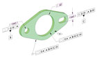
Dimensions may be directly or indirectly toleranced. Directly toleranced dimensions are those that are not basic. Directly toleranced dimensions may have a tolerance written next to the dimension, be limit dimensions or make use of a general title block tolerance. The drawing in Figure 1 illustrates common tolerancing methods. In addition to the tolerancing shown, tolerances may be unequal bilateral, or applied by using limits and fits tolerance symbols, or by referencing implied tolerances found in standards such as ISO 2768.

Limit dimensioning: 14.1 14.0

Plus and minus tolerancing:
    Unilateral: 30 +0.1/0
    Equal Bilateral: Ø12±0.1

Title block tolerance:
    Linear tolerance: ±0.2
    Applies to Ø100, Ø50, 30, 10 and two R3s
    Angular tolerance: ±2°
    Applies to the implied 90° angles


Basic Dimensions

Basic dimensions do not have a direct tolerance. The basic dimensions in Figure 1 are Ø76 and 40. By making these dimensions basic, the general tolerances no longer apply. Their tolerance is indirect. The tolerance is applied to the features on the part, not the dimensions. The basic dimension may be thought of as the goal and the geometric tolerance is the amount the feature may deviate from the goal.


Geometric Tolerances

Where geometric tolerances are used, they are applied to the feature rather than the dimension. The geometric tolerances are found in the feature control frames. In Figure 1 they are Ø0, 0, 0.1, 0.2 and three Ø0.3.

Even though there are 0s in some of the feature control frames, it does not mean that production must make perfect parts. The 0 tolerance applies only at one limit of size known as the maximum material condition (MMC) or the least material condition (LMC). Using 0 tolerancing actually provides production with more tolerance because it allows the acceptance of the best parts. This was not possible without GD&T.


Size Dimensions

The size dimensions in Figure 1 are Ø30, Ø100, Ø50, Ø12 and 14.1/14.0. The 10 and 30 dimensions use the dimension origin symbol in place of an arrowhead to indicate which surface functions as a “local datum feature” for inspection.


Enlarge this picture
<div>Geometric Tolerances</div>
There are 14 geometric tolerances. This table shows the tolerance symbols, describes what they control and whether or not they can reference datums. Source: Tec-Ease Inc.
Originally only direct tolerancing was used on drawings even though there never was a standard that could provide one clear meaning. Some of the problems with direct tolerancing include:

  • Multiple interpretations.
  • Tolerancing of points in space that cannot be verified, such as the center of a radius.
  • Tolerance accumulation.
  • Wedge-shaped tolerance zones where angles are toleranced in degrees.
Not all directly toleranced dimensions have these problems. GD&T was developed to eliminate these problems where they exist.

There are four categories of geometric tolerance characteristics: location, orientation, size (handled with direct tolerancing not shown in chart) and form. There is a hierarchy to these geometric characteristics. Location tolerances also control the orientation of features. Size also controls form.


Enlarge this picture
Figure 2
Figure 2A. Source: Tec-Ease Inc.
Datum features are labeled using a letter in a box at one end of a line and a triangle at the other. The triangle is associated with the feature that will serve as a datum feature to establish origins of measurement. Figure 2 illustrates a drawing where this approach has been applied. The old general titleblock tolerance has been replaced by a note making the dimensions that do not have a tolerance specified basic and a general profile of a surface tolerance that applies to the entire part unless it is overridden by a tolerance that appears on the field of the drawing. All measurements should be made from the datum reference frame established by datum features A, B and C. This part is totally defined with one clear meaning to anyone who knows how to read today’s prints.


Enlarge this picture
Figure 2B
Figure 2B. All measurements should be made from the datum reference frame established by datum features A, B and C. Source: Tec-Ease Inc.
GD&T has been evolving for decades and an understanding of it is essential for anyone who reads today’s drawings. There is no other standard for defining parts. GD&T is enabling the new technology in CAD, CNC software and automated inspection such as CMMs and 3-D scanners. Becoming educated in GD&T is an essential requirement for those who wish to compete on a global level.


Don Day
Don Day is president of Tec-Ease Inc. (Cherry Creek, NY), a mechanical engineer, professor emeritus and a standards developer. For more information, e-mail don@tec-ease.com, call Tec-Ease Inc. at (888) TEC-EASE or visit www.tec-ease.com.


|PrintEmail

Did you enjoy this article? Click here to subscribe to the magazine.


Most Emailed Articles

  1. GE to Open Manufacturing Technology Center in Michigan
  2. NIST Seeks Proposals for $35 Million in Grants for Measurement Science
  3. Americans View Manufacturing as No. 1 Industry for Economic Prosperity
  4. DGI Supply Acquires Tool Crib Supply
  5. Quality at 400 Blades per Minute
  6. Managing Changing Expectations: Corrective Action and Root Cause
  7. Quality 101: Surface Finish Measurement Basics
  8. Buick and Jaguar Tie for Highest Vehicle Dependability
  9. Quality 101:Calibrating Micrometers
  10. Study Finds Threats to U.S. Manufacturing
Top Searches
  1. Quality Management Systems
  2. quality control concepts
  3. CALIBRATION SOFTWARE
  4. "tolerances"
  5. visual inspection
  6. GD&T
  7. Product quality supervision
  8. cmm
  9. Face of Quality
  10. "reliability"
Most Popular Articles
  1. GE to Open Manufacturing Technology Center in Michigan 07/01/2009
  2. Understanding ISO 13485 01/02/2008
  3. Managing Changing Expectations: Corrective Action and Root Cause 05/05/2009
  4. Obama Awards $8 Billion in Loans for Advanced Automotive Technologies 07/01/2009
  5. Quality 101: Surface Finish Measurement Basics 09/01/2004
  6. ISO/TS 16949: 2009 Available in Electronic Format 07/01/2009
  7. Quality 101: Improving Quality Through Lean Concepts 11/21/2007
  8. Cerion Completes Purchase of Contech 06/29/2009
  9. NAM Supports Dispute Settlement Affecting U.S.-China Trade Relationship 06/30/2009
  10. Face of Quality: What is Quality Anyway? 05/27/2009
© 2009 BNP Media. All rights reserved. | Privacy Policy