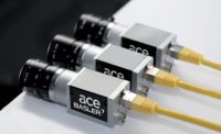
In case you haven't looked lately, machine vision technology has done a lot of growing up since the first systems arrived on the scene some 30 years ago. Once thought of primarily as inspection tools useful for separating good parts from bad, machine vision systems these days are increasingly being rolled out for more sophisticated factory uses.
While inspection and parts sorting are still important functions, the biggest bang-for-the-buck comes when data derived from machine vision systems are used for process diagnostics--to avoid the production of bad parts in the first place.
Today, the risk associated with undertaking a machine vision project is virtually nothing, provided the correct application can be identified. The average cost for a complete machine vision system ranges from $40,000 to $50,000. And when the technology is used as a yield enhancement tool, it is not uncommon for a machine vision system to pay for itself in anywhere from three months to two years.
Machine vision basics
In its most basic form, machine vision employs an imaging transducer that converts a spatial pattern of light corresponding to a scene into a digital map. Instead of a film image, as in photography, an electronic image is produced, which can be processed, segmented, modeled and analyzed. Similar imaging transducers are used in inexpensive digital cameras for the consumer market priced between $200 and $800. But the difference is that machine vision cameras are designed to deliver real-time data for computing-intensive, real-time analysis tasks. As the capabilities of microprocessors, digital signal processing and field programmable gate arrays improve, more of these functions can be performed in host-based designs or in "smart cameras," which are self-contained vision systems.
Machine vision companies offer application-specific solutions targeted at virtually every manufacturing industry. In some cases, different vendors target process and packaging applications within an industry. At the same time, other companies offer components--vision processors, frame grabbers, imaging boards, embedded vision systems and smart cameras--that serve as the framework for the vision engine. Still other suppliers specialize in machine vision software, which might include packages targeted at specific applications, such as LCD inspection, Ball Grid Array inspection, alignment and 2-D symbol reading.
Installation and use
For a first-time factory installation, it is critical that the staff becomes familiar with machine vision technology. Functional specifications for custom installation should be documented to establish requirements. The specification should include details on all production variables, including materials, colors, finishes, sizes, positioning and equipment, as well as define requirements such as graphical user interface and other man-machine interfaces, responsibilities and plant resources. In all cases, a formal acceptance test should be prepared to structure the buy-off procedure both at the vendor's facility before shipment, as well as upon installation at the final site.
Once familiar with the technology, assess the feasibility of the application. The computer operating on the television image in effect samples the data in object space into a finite number of spatial (2-D) data points called pixels. Each pixel is assigned an address in the computer and a quantized value, which typically varies from 0 to 255. The actual number of sampled data points will be dictated by the camera properties, the analog-to-digital converter sampling rate and the memory format of the frame buffer.
More often than not, the limiting factor is the television camera used. Since most machine vision vendors use cameras that have solid state photo sensor arrays of approximately 500 by 500 pixel resolution, certain judgments can be made about an application just by knowing this figure and assuming each pixel is approximately square. For example, given that the object being viewed takes up a 1 inch field of view, the size of the smallest piece of spatial data in object space will be approximately 2 mils, or 1 inch divided by 500. In other words, the data associated with a pixel in the computer will reflect a geographic region on the object of 2 by 2 mils.
The smallest spatial data point in object space can be quickly determined for any application using: X (mils) = largest dimension/500. This may not be the size of the smallest detail a machine vision system can observe in conjunction with the application. The nature of the application, contrast associated with the detail to be detected and positional repeatability are principle factors that also contribute to the size of the smallest detail that can be seen.
Factory machine vision applications can be broken into various generic tasks--verify that an assembly is correct, make a dimensional measurement on the object, locate the object in space, detect flaws or cosmetic defects on the object, read characters or recognize the object. Let's look at some of the applications one at a time.
Assembly Verification. Say you want to make sure that all of the features or components in an assembly are in place. First, look at the contrast, which is the difference in the shade of gray between what you want to discriminate and the background. If you can perceive that there is a high contrast between each of the features and the background or when a feature is in place or not in place, then the smallest feature one can expect to detect would cover approximately a 2 by 2 pixel area. If, on the other hand, the contrast is relatively low, then the feature should cover at least 1% of the field of view, or in the case of 500 by 500 pixels, a total of 2,500 pixels. Knowing the size of a pixel in object space, multiply that value by 2 or 2,500, depending on contrast, to determine the area of the smallest detectable feature.
Dimensional Measurement. To make dimensional measurements with a machine vision system, consider the 500 pixels in each direction as if they were 500 marks on a ruler. Just as a person who is making measurements with a ruler can interpolate where the edge of a feature falls within lines on a ruler, so too, can a machine vision system. The ability to interpolate, however, is application dependent. Claims of vision companies vary from 1/3 of a pixel to 1/10 or 1/15 of a pixel. As a rule, use 1/10 of a pixel.
What does this mean in conjunction with a dimensional measuring application? Metrologists have used a number of rules in conjunction with measuring instruments. The accuracy and repeatability of the measurement instrument itself should be 10 times better than the tolerance associated with the dimension being checked. This figure is frequently modified to 1/4 of the tolerance. Another rule is that the sum of repeatability and accuracy should be a factor of three, or 1/3 the tolerance.
How is the repeatability of a vision system established? Given the subpixel capability of 1/10 of a pixel mentioned in the example, an object that is 1 inch on a side, the discrimination (the smallest change in dimension detectable with the measuring instrument) associated with the machine vision system as a measuring tool would be 1/10 of the smallest spatial data point, or 2 mils (0.0002 inch). Repeatability will be typically + or - the discrimination value, or + or - 0.0002 inch.
Accuracy, determined by calibration against a standard, can be expected to run about the same. Hence, the sum of accuracy and repeatability in this example would be 0.0004 inch. Using the 3-to-1 rule, the part tolerance should be no tighter than 0.0012 inch for machine vision to be a reliable metrology tool. In other words, if the part tolerance for this size part is + or - 0.001 inch or greater, the vision system would be suitable for making the dimensional check.
As parts become larger and continue to have the same type tolerances, machine vision might not be an appropriate means for making the dimensional check based on the use of area cameras that have only 500 by 500 discrete photosites.
Part Location. When using machine vision to perform a part location function, expect to achieve the same results as those obtained when making dimensional checks. Most vendors whose systems are suitable for performing part location claim an ability to perform that function to a repeatability and accuracy of + or - 1/10 of a pixel. Using the example again, namely a 1-inch part, one would be able to use a vision system to find the position of that part to within + or - 0.0002 inch.
Flaw Detection. For applications involving flaw detection, contrast determines what can be detected. When contrast is extremely high, virtually white on black, it is possible to detect flaws of 1/3 of a pixel. These flaws can be detected, but not actually measured or classified. Since the flaw will not always fall on a single pixel but could fall across four neighboring pixels, the reliability of detecting a flaw smaller than a pixel is low. When detecting flaws that are characterized as geometric in nature, such as scratches or porosity, creative lighting and staging techniques can exaggerate the presence of flaws.
When contrast is moderate, the rule associated with assembly verification, namely that the flaw cover an area of 2 by 2 pixels would be appropriate. Classifying a flaw based on a pattern--and not just simply if it is brighter or darker than the background--with moderate contrast would require that it cover a larger area of about 25 pixels. Again, when contrast associated with a flaw is relatively low, as is the case with many stains, the 1% of the field of view rule would hold--it should cover approximately 2,500 pixels. If it is a question of trying to detect flaws in a background that is itself a varying pattern--stains on printed fabric, for example--chances are that only very high contrast flaws will be detected.
Benefits
Vision systems outperform human inspectors because once the inspection parameters are established, vision systems perform with consistency. Unlike people, who are typically 85% effective in visual detection of product quality concerns, vision systems catch virtually 100% of these conditions. Vision systems can be used to provide statistical insights into production variables, as well as catch all concerns, because they are fast enough to be applied in a 100% inspection mode rather than only a sample inspection mode.
Correct deployment of machine vision systems can yield significant benefits:
- Improved quality
- Reduced scrap
- Reduced rework
- Improved productivity
- Equipment breakdown avoidance
- Improved product reliability
- Improved customer satisfaction, along with reduced in-warranty repairs.
Opportunities for machine vision systems can be found throughout a manufacturing facility: incoming receiving inspection, forming operations, assembly operations, test, packaging and warehousing. Functions of many machine vision systems include location analysis/visual servoing, inspection for visual concerns, gaging, identification, recognition, sorting, counting and motion tracking.
- Success with machine vision deployment requires many of the same factors as the deployment of virtually every advanced manufacturing technology:
- Recognize that systemic changes will take place and that such changes have to be encouraged by top management
- Plant and line operators must be supported to ensure ownership of the technology
- All who will be impacted should participate in the project and transition process
- Schedules have to be realistic.
There is nothing to fear in deploying machine vision. The technology has matured, as has the industry. Benefits will be substantial when machine vision is deployed as a yield enhancement tool. Low cost vision sensors and smart cameras allow production and packaging line management to monitor the results of each value-added step so that problems can be eliminated before they reach customers.
TECH TIPS
- While machine vision systems are used to sort good product from bad, the actual bang-for-the-buck comes from process diagnostics.
- Machine vision cameras are designed to deliver real-time data for real-time analysis.
- Vision systems outperform human inspectors because once the inspection parameters are established, vision systems perform with consistency.

