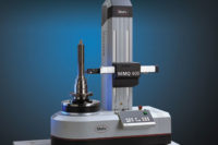
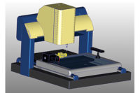
Successful introduction of products requires form, figure and functionality to be defined in the design process and verified in the manufacturing process. Traditional metrology methods rely on devices such as dial indicators, coordinate measuring machines (CMMs), laser scanners, and contact and noncontact surface profilometers to handle this task. But one problem with these devices is their limited ability to measure only one or, at best, two of the three parameters. In many metrology labs, in fact, it is common practice to use three different devices taking three separate measurements to check the three quality parameters.
Based on holographic imaging techniques, a new technology is able to measure form, figure and functionality simultaneously. Frequency modulated holographic speckle interferometry -- which grew out of military technology developed to map the shape of satellites from the ground -- has now been made practical for mapping the shape of complex parts in the factory. It is already being successfully used in applications including transmission and car corner components -- such as brake rotors, wheels and hubs -- ignition coils and disk drive read-write heads. The new technique relies on a specialized method of interferometry. Interferometers have traditionally been used in the optical industry for assessing the grinding and polishing of glass lenses. Interferometers today are generally amplitude-modulated devices and are sensitive to temperature changes and vibration. This is why the use of interferometers has generally not spread outside the optics and electronics industries, where environmental conditions can be accurately controlled. The new approach, by contrast, relies on frequency-modulated interferometry, which is able to filter out noise from the measurement, enabling it to be used on the manufacturing floor.
Similar to an optical CMM, speckle interferometry uses a digital camera and a telecentric telescope. It can view a part and capture images of the interference pattern. The camera resolution does not directly relate to the measurement accuracy, as it does with an optical CMM. In an optical CMM, each point on the object is mapped to a given pixel on the camera. With speckle interferometry, laser light that hits a given point on the object is imaged to many camera pixels. This is a one-to-many mapping as opposed to the one-to-one mapping of optical CMMs.
How it works
Speckle interferometry uses hardware components including a computer, a scientific-grade digital camera, a tunable laser -- a laser that emits light under several different, carefully controlled wavelengths -- an interferometer and a telecentric telescope. The size of the telescope is only limited by space and cost constraints for a given application. In one application of the technology, an 18-inch diagonal telescope is used, which is able to look at a 12- by 12-inch area.
In essence, the technique works by using the tunable-wavelength laser to flood the surface of a part with laser light, which bounces back into the digital camera. More than 1 million data points can be captured over a surface area up to 12 by 12 inches. Specialized software is then used to convert the captured data into a highly accurate 3-D height map of the part surface. This information can be used in the manufacturing process.
A number of automotive, aerospace and other design, development and manufacturing companies are using the new imaging technique. One such company, TRW Automotive (Livonia, MI) is using it to improve brakes for cars.
Before a brake manufacturer can focus on making surfaces as flat as possible, the flatness of the entire contact surface must first be measured to critical tolerances. Even more importantly, a brake manufacturer must determine how bearing surfaces interact when clamped together.
"Minimizing vehicle runout is a big issue with our customers," says David Horne, senior manager at TRW. "High runout will eventually produce brake vibration that can lead to high warranty costs at customer dealerships." Rotors can wear unevenly, producing disc thickness variation if the resultant lateral runout produced from clamping the rotor between the hub and wheel is too large. While each component may have low runout and meet all specifications individually, once they are clamped together on vehicles, the picture can be quite different.
At TRW, braking plates on some front rotors were found to cause a "turbine" noise on the vehicle. The company used speckle interferometry to map the entire brake rotor. The process, which required less than three minutes per rotor, revealed 12 raised peaks that were responsible for the noise. Once the problem was understood, the machining process was adjusted and parts were again measured to verify that the 12th order pattern had been eliminated.
"We realized we needed to take a systems approach to this problem and look at how these critical interfaces cause brake warranty issues," says Horne. "The brake supplier who can successfully understand the system and how it affects runout will have a competitive advantage, but to do so, you need specialized equipment and processes. With the help of this new 3-D imaging technology, we are gaining a much better understanding of how the whole foundation brake system works together."
TECH TIPS
- A technique developed originally for the military to map the shapes of satellites from the ground has been made practical for mapping the shape of complex parts in the factory.
- The technique works by using the tunable-wavelength laser to flood the surface of a part with laser light, which bounces back into the digital camera.
- Specialized software is used to convert the captured data into a highly accurate 3-D height map of the part surface.


