Machine vision systems help today's manufacturers improve quality and productivity.

With widespread adoption of quality standards such as ISO 9001 and increased pressures for "cost-down" automation, manufacturers in a broad range of industries have incorporated machine vision technology into their overall quality management practices. Vision systems are helping today's manufacturers improve quality and productivity by automating a variety of part inspection tasks with tremendous accuracy, speed and repeatability. At the same time, vision systems generate valuable inspection data at each step of the manufacturing process that quality engineers can use for statistical process control.
One of the most common applications for machine vision in quality control is gaging. Because vision systems measure part features within a thousandth of an inch, they are suitable for a number of applications traditionally handled by contact gaging.
Manufacturers implement vision-based gaging for a number of reasons. Speed is a primary driver. With contact gaging, it is impossible to keep pace with high-throughput production lines because measurements are typically performed on an audit basis. Machine vision systems, in contrast, are able to keep pace with the fastest production lines. They can perform thousands of measurements per minute, and are designed for in-line, 100% inspection.
Another key advantage of vision-based gaging is the fact that there is no physical contact with the parts being measured. This prevents damage to parts and eliminates maintenance associated with wear and tear on mechanical gage surfaces.
Finally, vision systems allow certain types of parts to be measured that cannot be gaged using contact methods.

System components
Vision products generally fall into three primary categories: vision
sensors, which are typically self-
contained, low-cost inspection devices; PC-based vision systems, which combine the power and flexibility of advanced programming with the simplicity of a graphical programming environment; and expert sensors, which deliver low-cost solutions to specific automation problems.
Regardless of form factor, there are a number of basic components common to most vision systems. These include a camera, processor, image analysis software, lighting and networking capability.
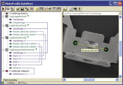
In a typical gaging application, a camera mounted above or to the side of a part captures an image of the part to be measured as it enters the field of view. The image is then analyzed using gaging software tools that calculate distances between various points in the image. Based on these calculations, the vision system determines if the part dimensions are within tolerance. If dimensions fall outside of tolerance, the vision system sends a fail signal to a controller, such as a PLC, that in turn triggers a reject mechanism to eject the product from the line.

Tools that measure up
Most of today's vision systems and sensors come equipped with a full library of preconfigured gaging software tools.
Gaging tools work by measuring the distance between edges in an image. An edge is any type of significant change in gray-value intensity in the pixel grid array that makes up an image. The change can be from dark to light, or light to dark.
In addition to calculating distances between edges, gaging tools measure angles formed by intersecting edges, as well as the size and location of holes in a part. Some of the most commonly used vision-based gaging tools include:
• Edge detection-locates edges in an image with subpixel accuracy and calculates the magnitudes and angles of edges.
• Caliper-performs multiple edge detections at high-speed to determine the width of part features.
• Blob analysis-performs highly repeatable measurements of the area, size and centroid of part features.
• Calibration-calibrates camera pixels to real-world engineering units.
The type of set-up/programming environment a vision system provides typically determines how easy gaging tools will be to use. Some systems offer graphical user interfaces that enable operators to apply gaging tools with point-and-click simplicity, whereas others may require at least some knowledge of an advanced programming language for tool set-up.
Repeatability: The real test
Measurement repeatability is a key indicator of vision system performance. Repeatability is key to maximizing reliable inspection yield and can be tested by presenting a part to the vision system for measurement at least five times without changing part position, lighting or any other variables. From this, a technician should be able to plot the repeatability of the measurements and make sure that any variance in the results stays within the measurement tolerance.
To meet the demands for higher throughput rates, improved product quality and increased yields, manufacturers will continue to rely on machine vision technology as a noncontact method to measure parts. Machine vision systems provide 100% inspection measuring parts at high speeds with a high degree of repeatability, and they can measure products that cannot be measured using mechanical gages. With so many different types of vision systems available today, quality engineers can easily find a solution that closely matches their specific application and budget requirements.
Mark Sippel is principal product marketing manager for In-Sight vision sensors at Cognex Corp. (Natick, MA). He can be reached at (508) 650-3000 or [email protected]. For more information, visit www.cognex.com.


