Increasing numbers of aerospace manufacturers are benefiting from model-based definition's quality assurance processes.
Model based definition (MBD) is not a new concept in the aerospace manufacturing industry. While it has been applied to product definition and manufacturing for years, its use as a fully implemented process for quality control only has been realized recently. Many companies are modernizing quality assurance processes to embrace MBD because aerospace's prime manufacturers are demanding it. Advancements in both software and hardware technologies are making it easier to put all the key elements in place, giving aerospace manufacturers the last piece of the puzzle for an enterprise wide system of digital product definition.
|
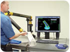
Applying model based definition to inspection offers a significantly leaner process on the way to a paperless airplane. Source: Verisurf Software Inc. |
MBD for CAD/CAM
The path toward the paperless airplane began years ago. Computer-aided design (CAD) was a significant step in that direction. Next, computer-aided manufacturing (CAM) allowed use of the CAD model for programming a digitally controlled device, applied most notably to computer numeric controlled (CNC) machining. Since then, numerous other manufacturing processes have used the CAD model and programming software for computer-controlled manufacturing. Along the way, manufacturers saw numerous challenges caused by using both a digital definition of the product via CAD, and nondigital means such as blueprints, hard master model tooling and mylars. This caused problems when digital and nondigital definitions were in disagreement, and organizations often struggled to sort out which one was correct. The solution was to switch to fully digital definition. With model-based definition, an organization eliminates ambiguities and creates opportunities for cost reductions and improvements in lean principles.
MBD for Quality Control
As aerospace companies have moved toward a fully MBD-centric system across the entire enterprise, a noticeable gap has been present in quality control. This is not to say it has been ignored altogether. CAD models have been used as the basis of definition for contoured parts for years. For shaped geometry, it is not easy to check a dimension against a blueprint, so aerospace manufacturers and their vendors have used coordinate measuring machines (CMMs) to gather data, along with various means of comparing the dataset to the nominal CAD geometry.
Boeing and other companies were seeking a more efficient and accurate method of comparing CMM point data to CAD models and providing other utilities such as best fit and reporting. These needs were very crucial to the manufacture and inspection of the tight tolerance wind tunnel models the company builds for them. This established an MBD approach from the beginning. Subsequently, model-based inspection has blossomed to where it is becoming the standard in the industry.
While model-based inspection has been used for quite some time, it often has been more of a last resort. CMMs have been relied on heavily for close tolerance parts and tools, but often they are used to verify dimensions whose values are read from a drawing, then inputted into CMM software or spreadsheets as nominal dimensions. In contrast, a purely model-based method uses the measuring system to align to the CAD model and report deviations between the part and the theoretical CAD geometry. Measurements are expressed as deviations to nominal values derived from the CAD model, and anything out of tolerance is identified. The elements of geometric dimensioning and tolerancing (GD&T) most often checked by this method are contour and hole position. Software also can check many other GD&T callouts including constraints such as flatness, concentricity and angularity.
|
This software imports a native Catia V5 model along with functional tolerancing and annotation and uses its tolerances in real-time to provide interactive GD&T. |

Hardware and Software Innovations
Making it easier to bring MBD to quality assurance are advancements in metrology hardware and software. Stationary, programmable CMMs continue to play a key role at aerospace companies, but they are now supplemented by new technology portable devices that are gaining popularity. Portable, articulating CMM arms, when pared with model-based inspection software, can turn first-article inspections into a 5-minute process instead of hours or even days often experienced using old methods. Also this type of technology is more accessible to small shops and to those with lower tolerances as seen in plastic parts and possibly even sheet metal (±0.030 inch typical contour tolerances).
For large-scale applications, other portable metrology devices such as laser trackers offer great productivity gains when using a model-based approach. With these technologies, inspection can be performed on the shop floor, on machine or aircraft, and do not require any labor intensive or time-consuming programming. This provides immediate information for on-the-spot decisions. Operators are no longer faced with only one choice in software provided by the device OEM. Third-party software offers a common software platform that may be used on all devices from all manufacturers. These modern metrology solutions provide productivity gains for:
-Part and assembly inspection.
-Digital jig build.
-Tool inspection, including periodic checks.
Interactive GD&T
In order to move to a fully model-based process for inspection, more must be considered than part geometry. One of the most significant challenges to eliminating drawings has been the need to identify tolerances and other characteristics of part manufacture. Notations are necessary to ensure form, fit and function of the component and assembly. Tolerances specify the degree to which any feature may vary from design and still sufficiently meet requirements. Because of the differing role each feature plays in the design, and also because of many other factors such as manufacturability and interaction with the assembly, a typical design may have as many different tolerances as it has features.
Historically a part is inspected with a measuring device, then tolerances are looked up and noted after the fact. Standard methods have been labor intensive and highly subject to human error. But MBD offers the ability to include all constraints within the model, tied to each individual feature.
New technology that brings MBD fully to measurement metrology, allows incorporation of GD&T from the model to be used actively for inspection. Software platforms are now available that use a fully toleranced model and recognize unique tolerances when moving from one feature to another, often referred to as interactive GD&T.
Chosen metrology software allows companies to import native Catia models complete with all GD&T-referred to as functional tolerancing and annotation in Catia V5-and actively use them while measuring with any choice of devices at their disposal, then perform all analysis and reporting on the shop floor. This has been a major leap forward in simplicity. The overall cost reduction to the assembly tool designs and the manufacturing of aerospace components, with the ability of shop floor mechanics to access equipment, measure and analyze directly to released engineering can benefit any aerospace company.
With this process, Boeing not only employs the native CAD model for manufacturing and quality assurance, but also gets the embedded GD&T constraints including datum targets, an important part of the inspection process. The datum, which identify the controlling features that align the measurement device-important to how the part is used in the assembly, weighting key features and their importance in locating each part-are used directly from the native model, and are even fed directly into the alignment routine of the metrology software.
Automated Inspection Routines
An even further step toward complete MBD is use of model-based, automated inspection routines, such as using the model with its unique GD&T for every given feature, along with a scripted routine running the measurement device for process control.
The latest in model-based inspection software allows operators of CMM devices, arms, laser trackers and stationary CMMs to set up routines, load the model and simply select "run" when ready. They are then prompted through a preset routine that completely controls the process. It ensures that parts are inspected the same way, in the same places, with the correct tolerances every time. Some platforms even allow the operator to use the same system for running a prompted routine on a manual device or to post the program out to a file that will run an automated (DCC) CMM. Customers and those who certify or audit quality control systems are pleased to see companies who apply this kind of process control.
Selecting A Model-Based Platform
When selecting metrology software to support model-based quality control, there are a few key capabilities to consider. The software must accurately and reliably import CAD models, ideally from native formats of Catia and Unigraphics, the most commonly used platforms in aerospace. Because both Catia and UG undergo frequent new releases, the software needs to be able to keep up with them. It also must handle large files and support all important CAD elements including imbedded GD&T.
When considering new software, test the software with sample models expected to be encountered in actual use. The software should make it easy to align to the model to begin inspection, it should allow for unique tolerances for each individual model entity-surfaces, hole locations, wireframe entities and points-it should have reporting capabilities that are flexible and easily customizable by the operator. Automated inspection routines also are an important feature. Evaluate the software's method to see how difficult it is to create routines. Operator-friendly software allows the customer to make changes, customize reports and program routines without requiring high-end programming or special skills.
Model-based definition is not only becoming the accepted process for quality control, but is becoming the preferred process for many reasons. Although, sometimes corporate culture is such that implementation can be challenging at first, organizations that modernize their processes to embrace the technology will quickly see the benefits. Besides becoming more of a requirement for companies wanting work from the top aerospace manufacturers, MBD capabilities in quality assurance are a must. Further-more, in these modern times where global collaboration is the norm, companies are going to find it impossible to ignore.
QUALITY Tech Tips
-With model-based definition, an organization eliminates ambiguities, and creates many opportunities for cost reductions and improvements in lean principles.
-When considering new metrology software, test the software with sample models expected to be encountered in actual use.
-Operator friendly software allows the customer to make changes, customize reports and program routines without requiring high-end programming or special skills.