Displacement Measurement Instruments
In 1881, Albert Abraham Michelson, winner of the 1907 Nobel Prize for Physics, invented an interferometer. The Michelson interferometer used a white light source with fixed and movable mirrors. Michelson interferometers have been used to measure distances or compare distances by counting interference fringes. With the invention of lasers, a single-frequency helium-neon laser replaced the white light source and two corner-cubes replaced the mirrors.A single frequency helium-neon laser beam is directed at a beam splitter. Half of the beam passes through to a movable corner-cube and the other half is reflected to a fixed corner-cube. The reflected beams return and combine at the beam splitter. When all the optics are exactly aligned and motionless, these two combined beams will interfere with each other to generate an interference fringe pattern. A small area photo detector counts the fringes. Each cycle of intensity change represents a half-wavelength of travel of the movable corner-cube. If the laser wavelength is known, the travel of the movable corner-cube can be accurately determined. The single frequency interferometer works well but is sensitive to noise. So, electrical noise and gain drift cannot be distinguished from motion.
A two-frequency interferometer uses a two-frequency helium-neon laser and mixes its two beams of two different frequencies to generate a carrier frequency. Therefore, the distance information is carried on AC waveforms, not DC. The two-frequency interferometer works well, however, it requires heavy permanent magnets and precision optical components to stabilize the laser, preserving polarization and minimizing the scattered light returning to the laser resonator. Because the system is bulky and has a large number of optical components, the cover must be removed from most machine tools to set up.
Laser Doppler Calibration System
The laser doppler calibration system uses a laser doppler displacement meter (LDDM), which is based on microwave radar technology, the Doppler Effect and optical heterodyning technology. The LDDM uses electro-optics, optical heterodyne techniques and phase-demodulators to obtain the position information of a movable corner-cube.The LDDM measures displacement based on illuminating a retroreflector with a helium-neon laser beam. The laser beam reflected by the retroreflector is frequency shifted as the retroreflector moves. Because the phase of the reflected laser beam is proportional to the position of the retroreflector, the change in position can be measured.
Polarization and stray light are non-issues, precision and special optics are not required. Windows can be inserted in the beam path and simple mirrors can be used to reflect the laser beam to any angle.
How It Works
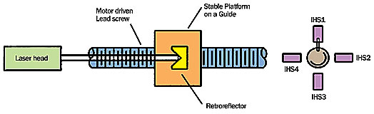
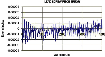
For lead/ball screw calibration, a blade mounted on the axis motor-driven lead/ball screw triggers the position sensors. For example, four position sensors can be used to collect four data per revolution. The position sensor sends a TTL pulse to a PCMCIA card, triggering data collection. The key to nonstop data collection is the external trigger and data collection synchronized with the TTL trigger pulses, allowing the data to be collected at the same time.With typical measured pitch errors with four position sensors, the lead screw pitch is 0.2 inch per revolution. This allows 20 data points per inch over 20 inches. In this example, the thermal expansion error is much smaller than the pitch error.
To calibrate an axis on a CNC machine, the laser head is mounted on the machine bed and the retroreflector, or target, is mounted on the spindle. The laser beam is aligned to be parallel with the axes in the same way as with conventional static laser calibration. Instead of programming the spindle beginning at the start position to stop at every increment with a 5-second dwell time until reaching the end position, the spindle is programmed to move continuously from the start position to the end position without any stops in between.
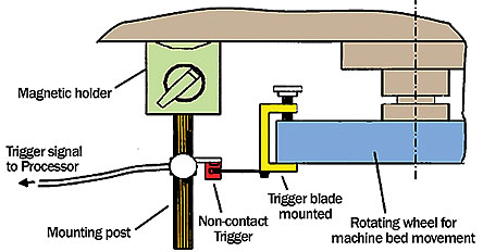
The position sensor can be mounted on the lead screw or the rotary wheel of the lead screw. The noncontact trigger is mounted on a magnetic holder with a post. The trigger blade is mounted on the rotating wheel of the lead/ball screw. For every revolution of the wheel, a trigger signal is sent to the PCMCIA card, which collects the data. For some machines, the trigger signal may come from the machine controller or encoder output.
Test Case
Using a LDDM-based laser calibration system with a high data rate PCMCIA interface card and an external trigger option, the data is collected nonstop and synchronous up to 10,000 data per second. A barometric pressure sensor, an air temperature sensor and a material temperature sensor for automatic compensation the speed-of-light change and material thermal expansion is standard with the laser system. The LDDM laser head was mounted on the table and the retroreflector was mounted on the spindle of a vertical machining center. A noncontact trigger was mounted on the post of a magnetic holder and a trigger blade was mounted on the rotating wheel.A notebook PC with high speed PCMCIA card was used for data collection. A special cable connected the LDDM Processor box output to the PCMCIA card and the trigger signal was connected to the LDDM processor box. In the LDDM software main menu, the 2-D time base button is clicked for data collection setup. The data rate, time duration and external trigger were selected. The maximum speed is up to 5 meters per second, and the maximum data rate is up to 10,000 data per second. The data age, time between the trigger pulse and latched displacement reading, was less than 100 nanoseconds.
In the test, two LDDM laser heads were separated by 4.25 inches and aligned in the Y-axis direction. The displacement data were collected with conventional static data collection at an increment of 2 inches over an 18-inch travel. The maximum error is 0.020 inch and the backlash is 0.005 inch.
In the same setup, the displacement data were collected using the nonstop synchronized external triggers. Data were collected over five bidirectional runs with an increment of 0.2 inch over 19 inches.
The two sets of LDDM displacement data were collected nonstop synchronously and simultaneously. The angular errors can be calculated by the difference of the two displacement errors divided by the separation. The maximum angular error is 8.5 arcsec. The maximum straightness error is 0.00012 inch.
Compared to statically collected data, nonstop data collection indicates the result is similar but it has more detailed features. Using the displacement data to compensate the machine errors, the final parts accuracy may be better using the nonstop synchronized data than conventional static data. Furthermore, time is saved when using the nonstop synchronous data collection for small measurement increments and large machines. Q
Quality Tech Tips
• Nonstop measurement and data collection allows many more measurement points, which provides substantially more detail and still cuts the amount of run time.
• By using the dynamic displacement error table, instead of the static displacement error table, contouring accuracy in theory can be improved.
• The Windows-based metrology software supplied with the LDDM based system supports automatic and nonstop synchronous data collection, which reduces measurement time by up to 50% or more.