
Figure 1 shows a 3-D volume representation of a BGA sample with micro vias and bond wires. Source: Yxlon
Shrinking device geometries in electronic and electromechanical components and microsystems enable continuous growth in complexity. These technologies drive the need to virtually cross-section a sample to simplify inspection. Computed tomography (CT) is the preferred way for 3-D analysis of state-of-the-art electro-mechanical solutions, as well as general complex assemblies. However, current CT systems suffer from major limitations in terms of speed and throughput, which are important requirements in industrial CT application.
While microfocus X-ray systems offer high resolution and advanced detail detectability, currently micro-CT is mostly used in quality control, research and development, and process monitoring, as its duration hinders application to higher sample volumes and production test. CT-applicability has extended from the lab to the production floor.
The CT solution described in this article enables a reduction in scanning and reconstruction times to less than 2 minutes in total. Results are achieved through enhanced synchronization of scanning algorithms and sampling rate of detectors. This in combination with a high-power microfocus X-ray tube and fast reconstruction algorithms supported by hardware accelerators leads to previously unknown speeds of 3-D X-ray inspections.
Continuous miniaturization and increasing quality and reliability demands drive the need for high- resolution and time-efficient X-ray inspection solutions. The first industries to require high-resolution CT were semiconductor packaging and electronic assembly. The requirements of these industries are now being observed in the automotive, aerospace and medical device industries.
Using the electronics industry as a baseline, the future needs of these other industries can be anticipated as well. With shrinking geometries, system complexity can be increased while development in packaging technology continues to address increasing I/O interconnects. With increasing interconnect complexity, key packaging technology parameters need to scale accordingly. New approaches, such as high-density wafer-level bonding or stacking of modules in a cube-like fashion, commonly lead to a further exploration of the third dimension in system integration.
Whether production testing, process monitoring, quality assurance, failure analysis or R&D, these technological advances lead to some significant changes in inspection requirements. Typically to ensure I/O interconnect integrity, automated optical inspections are widely used. However, with increasing numbers of hidden interconnects ranging from ball grid arrays (BGA) to contacts within encapsulated components (SiP), inspection techniques need to be deployed that visualize internal structures and component compositions.
High resolution X-ray inspection provides a valuable insight. Two-dimensional microfocus X-ray inspections were introduced in the early 1980s, leading to more than 2,500 system installations worldwide today. Two-dimensional inspections enable the assessment of hidden solder points including automated voiding calculations or in
Cone beam reconstruction. The microfocus 3-D µCT X-ray inspection methodology typically deployed is based on the cone beam reconstruction algorithm, called the Feldkamp method. Source: Yxlon
Conventional Microfocus CT
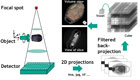
CT is the method of choice when performing 3-D analysis in research and development as well as failure analysis. Microfocus CT (µCT) 3-D X-ray inspection solutions have been available for more than a decade. The methodology typically deployed is based on the cone beam reconstruction algorithm, called the Feldkamp method. Radiation sourcing from the focal spot leads to an image of the object on an X-ray sensing detector. During a CT-scan a sample is rotated around 360 degrees in the beam of an X-ray tube. The rotation of the sample is performed in predefined steps. At each step the rotation stops for a short while and a 2-D X-ray image is taken. These images are called projections.The 3-D volume model is computed and visualized in a CAD-like environment for virtual cross-sectioning.
The main limitation for widespread use of µCT is found in typical image acquisition times of 1 to 8 hours where the reconstruction time is far less significant. The underlying cause of long scan durations is assigned to 2-D image quality. Among many other factors, such as focal spot size, geometric magnification, fast and sensitive detectors, there are two major image quality requirements directly correlated to scan duration: reduction of noise effects and limitation of longer-term shifts in geometry or performance.
Due to limitations in microfocus X-ray intensity for required small focal spot sizes, image integration for noise averaging leads to escalating scan times. These, on the other hand, demand a range of measures in order to limit shifts in geometry or performance over time (focal spot stability, X-ray intensity, thermal expansion). Other aspects also have an impact on µCT quality and resolution, such as optical distortion in image intensifiers or potential limitations in the definition of a µCT’s region of interest.
True X-ray Intensity Control
In microfocus X-ray tubes, electrons emitted at the filament are in essence accelerated toward a transmission target with focusing of the electron beam. Within the target material, a small proportion of the electrons’ kinetic energy is converted into X-ray. While in conventional microfocus X-ray tubes the emission current at the filament and the acceleration voltage are controlled, an alternative target technology allows assessment of the true current reaching the target. Based on a continuous feedback, the true X-ray intensity (TXI) technology adjusts emission currents in order to ensure maximum X-ray performance stability and hence consistent image quality. This leads to less stringent µCT averaging requirements for the acquisition of a single projection and, even more vital, to more stable projection quality over the 360-degree sample rotation.
Conventional µCT (left) and a new method (right) of a BGA with volume views (top) and views of a slice (bottom). For the conventional µCT illustrated on the left, 1,024 projections were acquired and 880 for the new method. Volume views show that both scans enable an in
High-Power Target
As up to 98% of the electrons’ kinetic energy is transformed into heat within the minute focal spot area, thermal stress can lead to target damage. Where higher X-ray intensity is desired, as in faster µCT, limitations in heat conductance require defocusing of the electron beam which degrades image resolution because of larger focal spot size.This shortfall has been addressed through the development of a high-power target. A ten-fold increase in thermal conductivity has been achieved compared to conventional transmission targets. Hence, high-energy electron beams can be kept in focus to maintain small focal spot size for high image resolution.

Further examples for high-resolution applications are depicted. Volume views allow detailed inspections of ball grid arrays (BGAs) and bonding wires. The slice through the illustrated 3 x 3 BGA segment show solder interconnects, micro-vias and voiding. The slice through a single BGA ball even shows the plating and filling of the micro-via below. Source: Yxlon
Detector and Reconstruction Technology
Reconstruction time strongly varies with the number of projections and required µCT resolution. Usually the reconstruction of a cube with 512 by 512 by 512 volume elements (voxels) can take around 15 to 30 minutes with standard reconstruction software. It was decided to use a supplier’s reconstruction solution with dedicated hardware accelerator boards achieving a 5123 voxel reconstruction for 540 projections within less than 2 minutes.New developments in digital X-ray detector technology have shown that advanced sensor arrays can deliver the high dynamics and resolution required for a fast µCT. It was decided to use a high speed X-ray detector with a pixel size well below 150 micrometers and a dynamic range better than 2,000:1 (contrast resolution is better than 0.5 %).
The resulting CT is based on major technological developments:
- True X-ray Intensity (TXI) control
- High-power target technology
- High-speed digital flat panel detectors
- Dedicated reconstruction solution
Continuous growth in electric and electro-mechanical system complexity with increasing exploration of all three dimensions drives the need for 3-D µCT. Technological advances addressing major shortfalls of conventional time-consuming µCT inspections have been described here comprising:
- True X-ray Intensity (TXI) control for maximum X-ray performance stability and hence consistent image quality.
- High-power target-achieving small focal spot sizes for high resolution at high X-ray intensity.
- High-speed digital flat panel detectors for fast image capture supported by dedicated solutions for fast reconstruction.
Tech Tips
Quality Online
Visit www.qualitymag.com and type “inspection” into the search engine to find related articles. Among the results you’ll find:- “Five Steps to Cutting Inspection Costs”
- “Enhance First Article Inspection”
- “How To Choose Inspection Software”
 and Digital X-ray Inspection Services")

