Critical dimensions in semiconductor manufacturing are in the deep sub-micron and nanometer range. Over time, specialized measurement systems suitable for these dimensions have been developed with the necessary accuracy and resolution for process control. As dimensions in industrial micro-manufacturing extend into the micro-scale, the technologies and capabilities of semiconductor metrology systems are enabling new generations of micro-manufacturing metrology systems.
Semiconductor scale integration-the number of transistors per square inch-has reached levels that might have seemed impossible only 10 years ago. For example, the complementary metal–oxide–semiconductor (CMOS) wiring in a Pentium4 microprocessor uses metal lines less than 150 nanometers (6 microinches) wide, and contains more than 300 million transistors-10,000 times more than the first microprocessor in 1984. In simpler terms, a greeting card that plays “Happy Birthday” contains thousands of times more computing power than the world’s first computer-the Sperry Univax.
Today, nearly 40 years after the development of the integrated circuit, semiconductor manufacturing technologies are starting to be used to make a wide range of industrial products smaller, faster, cheaper and smarter. Like all manufacturing processes, these micro-manufacturing techniques require metrology to control critical dimensions. These metrology systems need to be capable of highly accurate and precise measurements of very small features. They combine the best design practices of traditional industrial metrology systems with the leading-edge capabilities of semiconductor manufacturing to measure micro-scale dimensions of manufactured parts.
Semiconductor process metrology uses a number of techniques and methods to characterize and control the various patterning, deposition and etching steps used to form micro-scale features. Nearly all of these measurement techniques are noncontact, as the features being measured are far too small and too sensitive to be touched. In fact, many semiconductor wafer measurements are inferred from electrical or optical properties, rather than being measured directly.
Industrial micro-manufacturing shares many of these same requirements. Micro-fabricated parts often are too small or too fragile to be touched so conventional measurement tools such as tactile coordinate measuring systems (CMMs) are not suitable. Common examples in industry are wiring connections in flat panel televisions, drug-coated stents used to repair blocked coronary arteries and the printer heads in disposable ink-jet print cartridges.
Often, the size of features on these components are in the range of 100 microns or less, with tolerances of ±0.1 micron (100 nanometers) or less. To measure such features with precision requires a metrology tool with repeatability in the range of 10 nanometers (3 sigma) or better, for measurements within the optical field of view and point-to-point.
Metrology systems specifically designed for semiconductor applications that meet these requirements are typically not well suited to use for parts of other sizes or shapes. Recent advancements in microscope optics, illumination and related devices have enabled a new class of noncontact, optical micro-coordinate measurement tool that serves these advanced process metrology needs. These advanced features, combined with sound system design and powerful

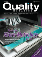
Micro-measurement of a flat panel display requires large XY stage travel to traverse a macro area with high precision. Source: View Micro-Metrology
Illumination Sources
Visible light microscopy systems typically used mercury arc or tungsten halogen light sources. While these light sources have their uses, they both require costly and complex arrangements to ensure adequate brightness without detrimental effects such as heating of the part being measured.Until recently, light-emitting diodes (LEDs) lacked sufficient brightness for microscopy. However, the latest high brightness LEDs are proving to be more than adequate for bright field objective magnifications up to 100X. LEDs are compact, cool operating, offer consistent color temperature, and their intensity is controlled by modulating either the input voltage or current.
LEDs usually can be mounted directly on the vertical illuminator of a microscope, eliminating the need for a remote lamphouse and fiber optic bundle. This arrangement is not only simpler, it also requires less maintenance and is suited to integration in tight spaces. Overall, LEDs provide a compact and inexpensive illumination package with many benefits for micro-measurement.

Micro-metrology systems require granite and other structurally sound materials to ensure the necessary positioning and measurement repeatability. Source: View Micro-Metrology
Considerations for Transmitted Illumination
Typical video-based coordinate measuring systems use transmitted illumination, or backlight, for measurement of most outside dimensions, through holes and for calibration. When used with a high magnification microscope, the transmitted light’s condenser optics must be carefully designed. There are several important criteria.First, the wavelength of the illumination must be selected to avoid distortion due to chromatic aberration. When full spectrum (white) light is used, the optics must be color corrected to prevent a change in focus with respect to wavelength. Chromatic distortion can show up as a colorful “halo” around the edges of the specimen. While color-corrected optics may be used to reduce these effects, the illuminator components become much more costly and complex to manufacture, and may be difficult to fit within the package size constraints of the measurement system. Monochromatic green light often is selected as a means of avoiding chromatic distortions, allowing a simpler, less costly optics design. Charge-coupled device (CCD) video sensors also are more efficient with green light.
A second key consideration is matching the numerical aperture (NA) of the illumination to that of the objective lens. The NA of the objective lens is directly related to the resolution of the system. The entire NA of the front lens needs to be filled in order to fill the aperture stop of the microscope, thus maintaining the resolution of the system.
Providing high NA illumination is not difficult if there is no restriction on the size of the condenser optics. However, in a coordinate measuring system, the space available for a sub-stage condenser lens beneath the part stage may be restricted. The cost and difficulty of manufacturing very large condenser lenses also must be considered. Thus, the condenser optics must be both compact and efficient.
For a general purpose micro- coordinate measuring system with multiple objective lenses mounted in a rotating turret, it may be necessary to provide an adjustable iris to modify the NA of the condenser to match the particular objective lens in use. The measurement software must be able to verify that the iris position is correct for each objective, and ideally would be able to control its position through the machine setup.

Dimensional microscopy of MEMS devices includes measurement of 2 microns wide “micro-actuator fingers” at 100X magnfication. Source: View Micro-Metrology
Automatic Controls
Another significant enhancement in microscope technology is the ability to control adjustments in the optical train automatically under computer control. Typically, controls such the aperture stop iris position are set once by the equipment supplier based on the optimum setup for a particular measurement. Once qualified, this position is not to be adjusted.Today’s automated microscopes allow these irises to be computer controlled so the user-defined program for a particular measurement can define the optical setup of the microscope. Putting these controls into the measurement software eliminates the possibility of error resulting from the operator choosing an incorrect setting, and allows the system setup to accommodate a wide variety of measurements using any available objective lens or light source.
Laser Autoranging
At the high magnifications needed to measure micro features, the depth of focus is typically very small. While a shallow depth of field helps to enhance resolution, it also means that focus has to be adjusted to bring each measurement site into its sharpest focus. If the change in focus between two measurement sites is large enough, it may be necessary to switch to a lower objective magnification to find good focus, then switch back to a higher magnification for fine focus and measurement. This switching process takes several seconds or more, slowing throughput significantly.An integral laser range finder can speed throughput by tracking and dynamically adjusting the focus position as the X-Y stage translates the part being measured. In this way, each new measurement site is kept in approximate focus during stage motion and only a single fine focus step is needed prior to each measurement.
When a pattern recognition system is integrated into the metrology software, the Move, Acquire and Measure time (MAM) can be further reduced by automatically running a search pattern to center the feature of interest in the field of view before fine focusing.
Integrating a laser autofocus system into a microscope does require special care, however, to prevent the introduction of distortion or loss of image brightness in the imaging system. Careful selection of beamsplitter optics and coatings, as well as the position of the laser in the optics train allow the laser to track surfaces reliably without degrading optical performance.

A microscope objective measures a micro-manufactured part held in a fixture. Source: View Micro-Metrology
Film Thickness Monitoring
Micro-fabrication techniques often involve the use of lithographic patterning, deposition and etching processes to form micro-features. For qualifying photomasks and stencils, and for controlling etching processes, a means of measuring photoresist or other thin film thicknesses (TFT) is needed. Given the need to monitor resist thickness at very specific locations on a part, the precision of a micro-CMM stage is required, making it all the more useful to combine film thickness and critical dimension measurement in the same system.Thin film measurement involves a unique set of optical metrology techniques. For nonconductive materials and semitransparent films, a noncontact optical technique such as interferometry or ellipsometry is best. Ellipsometry is best for very thin films, usually less than 1 micron, while interferometry techniques such as photospectometry can be used for thicker films.
Like the laser focus system, adding an integral photospectrometer to the microscope optics presents challenges. The TFT system must obtain adequate signal intensity to provide repeatable measurements, yet not starve the other sensors of light needed for measurements.
One solution is to package the spectrometer as close as possible to the beamsplitter position in the optics to minimize transmission losses. Laser autofocus, which is less sensitive to the full spectrum signal strength, can be placed above the TFT sensor in the optics train, followed by the video relay lens and camera.
Mechanical and Electrical Integration
Combining several types of sensors and advanced microscopy techniques into a single measurement system requires careful design and attention to details. Of critical importance are fundamental principles of sound mechanical and electrical design. Providing stable, precisely orthogonal and repeatable X, Y and Z motion, matching the materials used in the stages and machine foundation for similar thermal characteristics, and mitigating vibration and electrical noise to ensure stable operation-all of these design requirements must be exceedingly well attended to in a micro-metrology system.In addition, the metrology software must integrate the various sensors and microscope controls to enable automated machine setups that can be tailored specifically to the measurement requirement and called up on demand.
In summary, it is safe to say that the many, if not all, of the component technologies needed to build an ultra-high precision micro-metrology system are commercially available. However, the integration of those components into a practical high performance metrology tool requires considerable care and experience. When evaluating any micro-metrology system, it is important to examine these and many other details of the system design and its performance data to determine its ultimate capabilities.Q
Quality Online
For more information on microscopy, visit www.qualitymag.com to read these articles:- “Integrated Microscopy”
- “Look into Microscopy”
- “Mainstream Microscopy”

