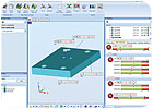
Least squares evaluation causes this good part to fail. Notice that the unconstrained profile failed as well as the A and A|B datum reference frames. Source: OGP
In the days before globalization of manufacturing, parts were designed, made and inspected in the same facility. Any disputes about interpretation of design intent during inspection were easily resolved by face-to-face discussion with the designer.
Today, with products being designed in one country and manufactured in others, such communications are difficult and unlikely to take place. With designers and inspectors in different time zones or unable to communicate in a timely fashion, the drawing is the only link between them.
This open-loop process can have costly implications with good parts being rejected or bad parts being accepted. It helps if the inspector has an understanding of the way the part is expected to function. A good drawing should provide this information. Geometric Dimensioning and Tolerancing (GD&T) makes it easier for designers to convey design intent so inspectors know how to do their measurements.
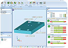
The same part passes when an ASME evaluation is applied. Source: OGP
What is GD&T?
GD&T is a communications protocol that is particularly helpful in a global economy where parts may be made in one part of the world and used in another. GD&T is increasingly being accepted as the best way of specifying 3-D design dimensions and tolerances on engineering design drawings. The currently recognized GD&T standard in the United States is ASME Y 14.5M (1994). The ISO parallel of ASME Y14.5 is ISO 1101. Although both standards have the same goal, they are not exactly equivalent, and it is important to know to which standard the drawing complies when measuring a part.As design software and machine tools have become more capable, increasingly complex parts are being designed. Designers use computer-aided design (CAD) software to design parts with specific dimensions that must be verified during the inspection phase of manufacturing those parts.
An example of a part with critical dimensions and tolerances is a plastic part designed to eliminate fasteners. By making a part with features that mate to another part, assembling those parts can eliminate the need for screws, reducing costs in parts and in assembly operations. However, sizes and positions of those mating features can be critical, with extremely tight tolerances. An inspector measuring those features, but referencing dimensions from the wrong positions may make the wrong decision. Properly specifying and using datums in GD&T can help avoid such errors.

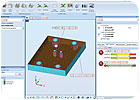
Least squares evaluation causes this bad part to pass due to the fact that it produces larger AMS at holes, which allows a larger mobility zone when datums are referred at MMC. Source: OGP
The GD&T Evaluation Environment
Inspection equipment measures parts for two main reasons-production acceptance, which is compliance to specified tolerances, and troubleshooting or problem solving of the manufacturing process.GD&T drawings typically reflect the first reason: they specify conditions, or tolerances, for part acceptance from a functional point of view. A drawing will have one or more datum reference frames (DRF) with tolerances located and oriented relative to each DRF. The ability to properly construct a DRF during the inspection process is crucial to the success of the evaluation.
To properly construct a DRF, it is important to strictly follow the rules as specified by the standards ASME Y14.5 and ASME Y14.5.1. These rules determine the sequence of the datums, the degrees of freedom that are eliminated, the constraints the primary datum has on the secondary and tertiary datums, and the mathematical fitting technique used to construct the individual datum simulators.
A typical old-fashioned measurement would simply execute a measuring program line-by-line and print the results. While this approach is acceptable for certain cases such as verifying sizes of features, it is not acceptable in all cases and will lead to incorrect results when the drawing contains DRFs that do not fully constrain all the degrees of freedom or have maximum material condition (MMC) or least material condition (LMC) modifiers attached to a datum reference.
In these cases the DRF can only be correctly determined after all of the measured points in that DRF are collected. This means that before starting the evaluation process, the nominal data (CAD) tolerancing information-datums, tolerance callouts and the measured data-must be available. This is called a GD&T Evaluation Environment.
The first step to working in this environment is to import the nominal data of the geometry typically available as a CAD model. It is important to understand that CAD design software and inspection software are two separate things.
CAD software may introduce uncertainties into the inspection process. One example is rounding of dimensions. If features used as datums have rounded dimensions, problems may result. The conversion process from native CAD formats to IGES, VDA, STEP or other formats may modify or lose some geometrical data.
It is important to understand that even if the metrology software claims that it is able to use native CAD formats, the interpretation of these formats is left to the measuring software and can become a source of discrepancies due to interpretation issues.
Typical problems encountered during CAD import are introducing form error on the nominal geometry or the incorrect location of the imported features. CAD software uses NURBS (B-splines) as a generic way of describing any geometrical surface and does not contain information if the shape is a cylinder, plane or a circle. That forces the task of nominal dimension calculations to the measuring software. During this process good GD&T software would have some tools available to expose any CAD import issues.
The next step is to import the measured data. If the data is collected by a CMM-like device, it is imported directly, but if the data is from a noncontact technology such as a laser scanner, there may be a need for intelligent data filtering. Intelligent data filtering means that the measured data is evaluated and, if needed, measurement noise is removed and the number of points is reduced. This process can reduce the uncertainties of the raw data quite significantly.
The same part fails when an ASME evaluation is applied. Source: OGP
Is Least Squares Enough?
Best-fitting is fundamental to the GD&T evaluation process. Best-fitting is used to correctly construct the DRF and then to optimize all the measured deviations. The difference between good and bad evaluation software is its ability to use the appropriate-not the most convenient-fitting technique.There are a number of fitting techniques available including least squares, mini-max, tolerance envelope, fitting with constraints, weighted best-fitting, maximum inscribed cylinder (circle), minimum circumscribed cylinder (circle), and tangent line or plane. These techniques exist for a reason and address specific goals. They can be applied to geometric element fitting or to point clouds to surfaces best fitting.
Most metrology software packages offer only the least squares evaluation technique, which would be fine for troubleshooting and problem solving. However, the least squares method produces larger actual mating size (AMS) holes and smaller AMS pins because it allows for a larger mobility zone when datums are referenced at MMC, which can lead to accepting a bad part. In fact, ASME Y14.5.1 does not refer to the least squares evaluation technique at all. It only refers to maximum inscribed, minimum circumscribed and minimum zone evaluation techniques.
Consider DRF creation. Assume evaluating a part with a plane for a primary datum ‘A’ and a perpendicular inside cylinder deriving a secondary datum axis ‘B.’ Using the least squares fitting technique for datum creation will produce an average plane instead of the necessary tangent plane. A tangent plane properly simulates the way the part will work. At the same time, a free least squares inside cylinder instead of a maximum inscribed cylinder calculated constrained to datum A, will lead to creation of a DRF which does not represent how the part functions. As a result there will be a systematic error for all of the results evaluated in that DRF and certainly a probability of bad parts being accepted and good parts being rejected.
Using ASME Y14.5 and ASME Y14.5.1 is the right way to go when specifying drawing requirements and evaluating parts for acceptance. In this process it is important to understand the need for a global approach by using a precision GD&T environment. Using the right best-fitting technique as specified in the ASME Y14.5.1 is crucial. Failing to do that will lead to accepting bad parts and rejecting good ones. Making bad part decisions is not good for business-particularly when trying to minimize costs.Q
Quality Online
For more information on GD&T visit www.qualitymag.com to read the following articles:“Adding Value for True Position”
“Defining GD&T”
“GD&T Improves Inspection”