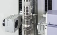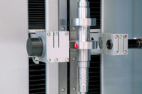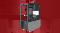
Optical shaft measuring systems, such as matrix array systems, can be successful for transmission shaft applications. A number of checks can be performed, including diameter across the shaft, angle of tapers, depth of grooves and run-out of a shoulder to the overall axis of the shaft. Source: Mahr Federal Inc.
Shafts are everywhere. Whenever a part is made to turn on an axis, a shaft is usually involved. Shafts can be tiny enough to turn the gears in a watch or large enough to spin the propellers of huge ships, and they can contain any number of functional features, such as gears, splines, threads, tapers, grooves and bearing surfaces-all of which have associated critical dimensions. It is not unusual, for example, for a single, modest-sized shaft for an automotive transmission, to require more than 60 dimensional checks during its manufacture.
Dimensional checks on shafts and shaft features are done with every type of gage imaginable, from basic handheld devices, such as micrometers and snap gages, to high-end coordinate measuring machines (CMMs). However, there is growing popularity for a loosely defined class of shaft measuring systems that can accomplish these checks faster than other methods, and do so directly on the shop floor where the shafts are made. Frequently used in Europe, shaft measuring systems are gaining U.S. popularity in a number of high-volume applications.

Manually operated, usually with the help of a computer interface for electronic data capture, systems such as this one consist of a series of measuring modules mounted on a precision bed next to a lathe-like part mounting assembly. Depending on the configuration, such systems can handle a number of basic measurement tasks. Source: Mahr Federal Inc.
Different manufacturers offer a variety of systems able to measure different ranges of parts, but the general spread is shafts as small as 25 millimeters, or 1 inch, in length up to 1,000 millimeters, or 40 inches, in length; 125 millimeters, or 5 inches, in diameter; and 50 kilograms, or 100 pounds, in weight.
As already noted above, shafts can have many different types of functional features. In terms of shaft measuring systems, however, current technology is pretty much constrained to look at features that all shafts have in common, such as lengths, diameters, length between features, diameters of features, run-outs to various axes or taper. It also is possible to measure more derivative parameters, such as cylindricity. Beyond that, one quickly finds the limitations of the technology.
Another criterion is cycle time. If a measurement needs to be done and feedback to a producing machine generated before expensive scrap parts are made, then this technology addresses the need. With optical machines achieving part measurement times in the 1 to 2 minute range, real-time correction to the manufacturing cycle is possible.

Line scan technology creates an image of part dimensions by means of a series of lines. To measure edges and shoulders, the line sensors need to be tipped relative to the axis of the part. Source: Mahr Federal Inc.
Benefits of Shaft Measuring Systems
Shaft measuring systems compete with handheld gages on one side and CMMs on the other. Compared with handheld gages, dedicated shaft measuring systems offer a much greater degree of efficiency in that they can make a number of checks with a single setup and a single scan. There also is less operator involvement and greater accuracy.Compared with CMMs-by far the greatest competitor for high-volume U.S. applications such as automotive-shaft measuring systems offer the benefit of speed. And while CMMs are generally found in dedicated measurement centers or metrology labs, shaft measuring systems are, by and large, robust enough to operate on the shop floor within easy reach of production equipment, and are able to provide direct feedback to those machines. Combined with faster measurement speeds, this means an increase in both the number of features and the number of parts that can be checked during a production run-and that means improved process control.
Another, less-definable benefit, is that CMMs are inherently very flexible machines that can measure everything. More dedicated in function than a CMM, shaft measuring systems can offer easier programming and operation. Shaft measuring systems also operate in the same 2-D axis of motion as the lathes that make shafts, while CMMs operate within a 3-D Cartesian envelope. While measurements made by CMMs cannot be said to be less accurate, it can be argued that measurements made with compatible geometry can provide better integrity and repeatability.

Due to the defined nature of shafts, programming optical shaft measuring systems can be intuitive, easy to learn and easy to maintain. Source: Mahr Federal Inc.
Types of Shaft Measuring Systems
There are three basic types of shaft measuring systems currently in use. The first is not really a system, but rather a collection of handheld gages mounted onto a dedicated fixture and often mechanized to engage simultaneously to provide a number of dimensional checks. Such constructions are most often built for specific shafts. While they offer economy and speed of measurement for their specific applications, they are oftentimes difficult, if not impossible, to modify for different tasks. For a company that produces thousands of the same shaft part day in and day out over long runs, such an option can be an excellent choice.For those who need more flexibility in the measuring process but cannot justify a higher-end optical system, the second type of shaft measuring system is a more modularized and generalized version of the fully dedicated gage described above. Manually operated, but usually with a computer interface for electronic data capture, these systems consist of a series of measuring modules mounted on a precision bed next to a lathe-like part mounting assembly.
Depending on the configuration, these systems can handle a number of basic measurement tasks, such as length, diameter, run-out and axial run-out, as well as more complex measurements, such as distance, width of recesses, depth, diameter of recesses, roundness, taper, angle, radius, intersection point and position of cross holes.
Such systems are a good option for smaller shops that produce a variety of parts in shorter runs and require both flexibility and ease of use in their measuring system. Typical parts measured on these manual systems include crankshafts and camshafts, gearshafts, toothed racks, outer races, hollow shafts, driveshafts and control pistons. These systems offer the benefit of a single measuring instrument providing a multitude of measuring tasks. They are easy to use and can be located on the shop floor while providing high measuring accuracy. They can be acquired on a modular basis and readily configured for different parts and do not require recalibration between parts.
But these days, when an operator refers to a shaft measuring system, he is most likely referring to newer, fully automated, optical shaft measuring systems. Such systems are designed to facilitate precision control of complex turned parts. Able to operate both in the lab and on the shop floor, optical shaft measuring systems allow for the measurement of many characteristics on turned parts in seconds and without contact. Fully automatic measuring sequences eliminate operator influence from measurement results and, in many systems, graphic interfaces simplify programming and use.
As the trend continues toward increasingly smaller features and increasingly tighter tolerances, the market will see more demand for these noncontact, nondestructive measuring devices that are easy to program, quick to measure and can accommodate a wide range of parts.

The use of high-resolution, matrix array or CCD cameras is more recent and has been made possible by advances in computer processor technology. This system can complete many different measurements from a single image. Higher resolutions make measurements more stable and accurate, and allow for measurement of much smaller features than the calculated image of a line scan. Source: Mahr Federal Inc.
Line Scan vs. CCD Technology
Optical shaft measuring systems use two basic technologies: line sensors and matrix cameras. Both use backlit or silhouette imaging. Therefore, if the system cannot see inside a feature, it cannot measure it. But beyond that, there are other advantages and disadvantages that need to be considered.Line scan technology is fast and has been proven in the field for more than 20 years. As its name implies, line scan technology creates an image of the part dimensions by means of a series of lines. To measure edges and shoulders, the line sensors need to be tipped relative to the axis of the part. Part and feature diameters are indicated as a series of connected points or dots, and measurement computations are made with this calculated image of the part. Because of the low resolution, small features are harder to measure.
The use of high-resolution matrix array, or CCD cameras, is more recent and has been made possible by advances in computer processor technology. While faster than other measurement methods, matrix measurements can still be slightly slower than a line sensor due to the larger amount of data to be processed or the number of places where camera images need to be taken. On the other hand, many different measurements can be completed from a single image. Higher resolution makes measurements more stable and accurate, and allows measurement of much smaller features than the calculated image of a line scan. The best matrix systems virtually eliminate all operator influence and, to ensure the highest possible accuracy, take multiple images per measurement.
Because matrix array technology uses an actual, highly magnified image of the part, any dirt or problems with the part are instantly visible. While this can be slightly disconcerting-line scan images appear to clean the part rather effectively, and it is a reminder that good measurements require clean parts.
Whether or not a universal shaft measurement system is right for the application depends on the careful analysis of several factors, including the size and weight of the part, the number produced per shift and per run, the number and type of checks required, the current means of doing these checks and-in the case of CMMs-whether there are other demands for those systems.Q


