In order to eliminate the “feel” part of the measurement, the designers of micrometers have incorporated a ratchet or friction thimble mechanism. This is an attempt to ensure more consistent contact pressure and eliminate human influence. Source: Mahr Federal Inc.
Conceptually, the dimensional measurement process is quite simple. You get a drawing for a part-an electronic computer-aided design (CAD) file, blueprint, napkin doodle or whatever-which indicates certain critical part dimensions and tolerances: a particular diameter, for instance, must be 2.2370 inches ±0.0002 inch. All the manufacturer needs to do is to machine the parts to that dimension, then measure them to document that they are within the specified tolerance. What could be easier than that?
Probably a lot. Not only does the tolerance of the part need to be considered but also the number of parts to be measured, the time needed for measuring, the skill of the operator, the environment of the measurement and how much money is to be spent. All these questions go into finding the right dimensional gage for the process.
The subject is complex and there is no one-size-fits-all solution, even for the same dimension on the same type of part, measured under similar conditions but in different shops. There are, however, some broad distinctions that can be made in terms of levels of precision, speed and throughput required that can help make the gage selection and measurement process easier.

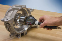
Universal length measuring instruments provide high accuracy internal and external measurements directly on the shop floor. With a direct measuring range of up to 50 millimeters (2 inches) and an application range of up to 100 millimeters (4 inches), these bench gages are capable of measuring parts and critical levels off masters as long the environment can support the measurement. Source: Mahr Federal Inc.
Measuring vs. Gaging
While we often use the terms “measuring” and “gaging” interchangeably, there are times when measuring is appropriate, and other times when gaging is the way to go. What’s the difference?Measuring is a direct-reading process in which the inspection instrument consists of or incorporates a scale-a continuous series of linear measurement units (such as inches or millimeters), usually from zero up to the maximum capacity of the instrument. The workpiece is compared directly against the scale, and the operator counts complete units up from zero, then fractions of units. The result generated by measuring is the actual dimension of the workpiece feature. Examples of measuring instruments include steel rules or scales, vernier calipers, micrometers and height stands. Coordinate measuring machines (CMMs) might also be placed in this category.
Measuring tools such as calipers and micrometers are used by machine shops everywhere since they offer the flexibility to measure a number of different features relatively quickly and easily. With these types of hand tools, it is fairly easy to measure a wide range of parts having tolerances in the order of ±0.001 inch.
Gages, in contrast, are indirect-reading instruments. The measurement units live not on a scale, but off-site (in a calibration lab somewhere), and a master or other standard object acts as their substitute. The gage thus evaluates not the dimension itself, but the difference between the mastered dimension- such as the specification-and the workpiece dimension.
Gages bring a whole new level of measuring capability to the operator of the gage. What might have been a difficult ±0.001 inch tolerance for a caliper to measure is now a piece of cake with a comparative gage. Depending on the configuration, tolerances of ±0.0005 inch or better are easy for the dedicated gage.
Also, gaging tends to be faster, both because it is less general purpose in nature, and because the operator need observe only the last digit or two on a display, rather than count all of the units and decimals up to the measured dimension.
For anything resembling a production run, gaging is almost always required. But where single part features must be inspected, measuring devices still tend to make more sense. In practice, most shops will find they need some of both types of devices.

The humble caliper is a surprisingly versatile tool for a wide range of general purpose distance measurements. These water-resistant digital calipers are designed for use in extreme production environments in accordance with the IP67 standard. Source: Mahr Federal Inc.
Ten-to-One vs. MSA
Years ago, when tolerances tightened and the importance of proper inspection was realized, gage users needed a way to ensure the tool was appropriate for the process. Since most tighter tolerance parts were driven by military applications, many military standards were developed. Derived from one of these was the “ten-to-one” rule which recommended that the measuring instrument resolve to approximately ¹⁄10 of the tolerance being measured.In today’s world of tightening tolerances this may not always be achievable, but it is a good goal. For example, if the total tolerance spread is ±0.0005 inch, the smallest increment displayed on the gage should be 0.000050 inch or better. But rules of thumb do not always cut it. Today the entire measurement process needs to be studied. These evaluations can assign errors not only to the gage but to the operator, the environment and other areas associated with the process.
A measuring system analysis is a very structured way of evaluating the process to determine if a gage is capable of meeting the needs of the measurement application. The ten-to-one rule is like the buggy whip in the metrology world, but it is still often used as a guide for narrowing the process for selecting the right gage for the application.

The caliper is an extremely versatile and useful tool for making a wide range of distance measurements, both ODs and IDs. The caliper can span from two inches to four feet, depending on the length of the scale. Source: Mahr Federal Inc.
Selecting a Gage
Process considerations aside, ultimately, one has to decide how to verify the dimensions of the part. A good approach is to think in terms of levels of increased performance. Below are classified levels of performance of shop floor handheld gaging used by an operator to qualify parts.Level 1: Basic shop tools. Versatile, low precision and low cost.
The caliper is a versatile and useful tool for making a wide range of distance measurements, both outside and inside diameters (OD/ID). The caliper can span from zero inches to four feet, depending on the length of the scale. External measurements are made by closing the jaws over the piece to be measured, while internal measurements are made by opening up the inside diameter contacts.
While the caliper is a versatile tool, it is not one of the most precise. Skill is required for positioning the tool and interpreting the measurement result. As the operator develops a “feel” for the tool, his measurement results will become more consistent. While the digital caliper may take some of the guesswork out of reading the measured value, it still requires skill on the part of the operator to apply the tool properly to the dimension being measured. The humble caliper is a versatile tool for a wide range of general purpose distance measurements.
A small step up in accuracy and performance-but with a shorter measuring range-is the micrometer. The basic micrometer is probably the second most popular and versatile precision handheld measuring tool on the shop floor. While the most common type is the outside diameter style, the same measuring principle also can be used for inside diameters, depths and grooves. With so many options for holding the spindle, and alternate contact points available, micrometers can satisfy an endless number of measurement applications.
The biggest problem with micrometers-as with calipers-is that measurements are subject to variation from one operator to another due to “feel” or inconsistent gaging force, and other subjective factors.
The micrometer is a contact instrument, and sufficient torque must be applied to the micrometer barrel to make good positive contact between the part and the instrument. In order to eliminate the feel part of the measurement, the designers of micrometers have incorporated a ratchet or friction thimble mechanism. This is an attempt to ensure more consistent contact pressure and eliminate operator influence.
The process of aligning the micrometer, adjusting it to the size of the part and then closing the contacts to make the measurement takes time and skill. And the resulting measurement may not be accurate enough for the tolerance that is to be measured.
Thus, there are some constants with both calipers and micrometers. On one hand, they are versatile and can measure a wide range of different parts. On the other, they are at the mercy of the operator using them.
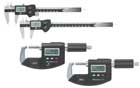
Calipers and micrometers are easily the most popular and versatile precision handheld measuring tools on the shop floor. The biggest problem with these instruments is that measurements are subject to variation from one operator to another due to feel or inconsistent gaging force, and other subjective factors. Source: Mahr Federal Inc.
After tolerances reach the 0.0005-inch level, one begins to enter the region where a comparative gage such as a bench stand, snap gage or ID/OD gage is required.
Let’s look at one specific example. Say operators are checking a shaft diameter on the computer numerical control (CNC) lathe after the manufacturing process is complete. Micrometers might be the instrument of choice, and maybe could resolve to 0.00005 inch or so. But let’s say there is a need to check the diameter at multiple locations to ensure there is no taper in the part. Just picture the operator bringing the micrometer over, getting it to nearly the right size, adjusting the torque to the correct gaging pressure, removing the micrometer to read the size, then moving on to the next location: this process wastes time and money, not to mention incorporating the influence of the operator. A better choice would be an adjustable snap gage.
Insert a snap gage onto a workpiece and one will quickly understand how these effective, fairly simple OD gages got their name. Once overcoming the “locking” spring tension, the part suddenly slips in against the backstop, contacting it with a good, healthy “snap.”
Snap gages can be hand held to measure workpiece ODs while still on the machine or can be mounted on stands for use with small parts. The heart of the tool is a simple C-frame casting, and measurements rely on a direct in-line 1:1 transfer of motion. These factors make snap gages simple, reliable and fairly inexpensive.
With a standard dial indicator installed, the measuring range of an adjustable snap gage is typically 0.020 inch. When combined with a digital indicator, a high precision snap gage can resolve and accurately measure to 50 micrometers. This provides the performance needed to reliably measure those ±0.0005 inch tolerances.
Aside from the higher performance of the snap gage, other key features are the speed of the measurement and the lack of operator influence. There is no need to adjust the gage to the right size, or to ensure the gage is square to the part, or to apply the right force on the part. It is all built into the gage. Thus, snap gages improve performance through speed and accuracy.

Once tolerances reach the 0.0005-inch level, operators enter the region where a comparative gage such as a bench stand, snap gage or ID/OD gage is required. Source: Mahr Federal Inc.
The comparative gages mentioned offer some adjustability, allowing them to be set for comparative measurements on a number of particular sizes. For example, a mechanical snap gage may have an inch of range adjustment but its actual measuring range around the master setting would be ±0.020 inch. This combination of adjustability to size and short measuring range provides a good balance of versatility and performance.
But as is the case with most dimensional measurement, the shorter the measuring range, the higher the performance. This is the case with fixed plug gaging. This type of gage is made specifically to measure a certain size. Examples include air gages and mechanical plug gages. (Air gages, by the way, were the first high precision gages brought to the shop floor, back in the 1940s.)
These gages are made to simulate the dimension being measured to within 0.020 inch or so. The sensing unit is set to a master and the operator compares the measured part to the standard. Very high resolutions can be obtained with this type of gaging, down to 5 micrometers with good accuracy. In addition to excellent performance, this type of gaging also is the easiest and fastest method for an operator to use. Because the gage fits so closely to the part, the operator has to simply put the gage on the part and the gage will set itself. So there is virtually no operator influence, and thus, very high throughout.
In terms of utility, air gaging or fixed plug gaging is quite capable of measuring a shaft tolerance to ±0.0002 inch, on the machine and in a machine shop environment.
Level 4: Linear length gages. Highest performance, lowest throughput.
As noted, the focus of this piece is shop floor dimensional gaging. But there is one more level of gaging that is the ultimate in precision and offers good versatility, but may not be the fastest method. However, if the goal is to get the best performance, then a shop-oriented linear length machine may be the solution.
A linear length gage can be thought of as a bench-mounted digital comparator but designed for rigidity, stability and accuracy. These bench gages are capable of measuring parts and critical levels off masters as long the environment can support the measurement. Just as the comparator offers versatility, the linear gage does the same. But in certain cases, such as reference pins, valve stem and the like, this type of gage offers a good balance of performance and versatility.
But once into the microinch resolutions these gages can offer, then you must also have the proper conditions to support the measurement. That means controlling other sources of error, such as the operator, masters and the environment. That is a subject-enhancing measurement precision-for another time.Q
Tech Tips
Quality Online
For more information on dimensional measurement, click on the following:“Air Gaging Gets Better with Age”
Case Study: “Dimensional Measurement Success”
Q-cast Podcast: Five Steps to Complete Your Measurement Process
Quality 101: “Proper Care of Handheld Measuring Tools”