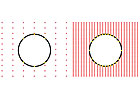
Figure 1: The image on the left shows a feature measured with a scanner with a large field-of-view. The image on the right shows a feature measured with a standard field-of-view scanner with a long standoff distance. With increased point density, the accuracy of features measured with the long standoff distance is much higher than that of a feature measured with large field-of-view scanners. Source: Nikon Metrology Inc.
Speak with any optics expert about improving the accuracy of today’s common 3-D laser scanners and you will be subjected to a barrage of abbreviations and terms such as CCD, CMOS, base angles and diffuse vs. spectral reflectivity, to name a few. When it comes to improving the accuracy of coordinate measuring machine (CMM)-based laser scanners, it is important to avoid putting the cart before the horse.
For manufacturers that must hold extremely tight tolerances on their parts, tactile measurement often is their only means of highly accurate measurement. Since the introduction of the first laser scanners in the late 1970s there has not been a huge, chasm-crossing breakthrough in the accuracy of noncontact laser scanners that would allow manufacturers of tightly dimensioned parts to abandon classical touch-trigger and analog scanning methods.
Today, manufacturers incorporate laser scanning into their quality control processes because they realize the inherent speed and measurement coverage advantages of laser scanning. The advantages that increased speed and coverage provide outweigh the expected slight degradation in accuracy.

With increased distance between the surface being inspected and the scanner, this scanner deftly navigates around complex surface geometry and maneuvers around tricky holding fixtures. Source: Nikon Metrology Inc.
A New Scanner
Rather than tackle the physical limitations of laser scanner triangulation with respect to accuracy, laser scanner manufacturers have been pouring their research and development efforts into a variety of probe enhancements. These probe enhancements include everything from increased field-of-view size and improved performance on dark and shiny parts to scan point interpolation. Along with these scanner enhancements, a unique new type of scanner has emerged-the long-standoff scanner.Point interpolation is a great marketing tool, although one questions the need to have millions upon millions of points scanned when upwards of 99% of those points will be filtered away to create a manageable file size for today’s common PCs and graphics cards. Even centuries ago, the ancient Greeks knew that only three points were required to define a plane, and that more than that can be overkill.
Making strides toward surface independent scanning has been another hot topic in the laser scanner manufacturer’s circle, although the issue of collecting data on dark and shiny surfaces often becomes a software issue rather than a hardware issue.
Increasing a scanner’s field-of-view is a great way to improve laser scanning throughput, but many laser scanner manufacturers tend to simply tweak their scanner’s optics and calibrate a larger field-of-view with the same pixel array leading to a huge degradation in spatial point resolution. An innovative approach to counterbalance the accuracy and spatial point resolution degradation is simply offsetting a scanner’s calibrated field-of-view but not changing its field-of-view dimensions.

Parts such as automotive instrument panels, transmission cases and even bodies in white are uniquely suited for long-standoff scanners. Perched well clear of the part, a long-standoff scanner is used for tricky parts with complex surface geometry. Source: Nikon Metrology Inc.
Overcoming Limitations
While there are physical limitations when manufacturing long-standoff scanners, the limitations are fairly easy to overcome. For example, increasing the power emitted by the laser is a simple way to compensate for the added triangulation distance. By keeping the same pixel array and calibrated field-of-view as its short-standoff cousin, the spatial point resolution of a long-standoff scanner mirrors that of a short-standoff one.What this means is improved accuracy when inspecting surface profile and improved accuracy over conventional scanners with regard to feature measurement with larger fields-of-view. Figure 1 shows the typical point dispersion for a scanner with a larger field-of-view vs. that of a properly calibrated long-standoff scanner. With a tighter spatial point resolution, the resulting size and location of any given feature will be measured much more reliably with a long-standoff scanner.
Before quality managers start demanding long-standoff scanner retrofits on their coordinate CMMs, it is important to keep in mind that their short-standoff cousins still have their place in quality control.
Consider a bridge-style CMM with a 1,000 millimeter x 1,500 millimeter x 1,000 millimeter volume in its X, Y and Z directions. With a typical short-standoff scanner, the maximum volume of a part that could be inspected on the CMM would be about 700 millimeters x 1,200 millimeters x 840 millimeters. With a typical long-standoff scanner, the operational measuring volume of the CMM would see a steep decrease to approximately 500 millimeters x 1,000 millimeters x 750 millimeters.
Figure 2 shows the expected reduction in measurement volume on a bridge-style CMM with a short-standoff vs. a long-standoff scanner. Such a drop in measuring volume could be hard to handle for quality control departments that already rue the day they opted for a smaller CMM instead of foreseeing future demand and investing in a slightly larger model.
CMMs, however, come in a multitude of styles and configurations. While the typical volume of a bridge-style CMM may preclude it from being retrofit with a long-standoff scanner, horizontal arm and gantry-style CMMs are ideal candidates for long-standoff scanners. Much of the reason that larger volume CMMs are ideal for laser scanning has more to do with application than it does with volume.
Consider a welded sheet metal assembly from an automotive OEM. To the casual observer it may be just a big heap of twisted metal, but an engineer with a technical eye will see the part as geometric dimensioning and tolerancing (GD&T) poetry with every hole, slot and radius a key component in its fit and function. If this assembly is to be properly inspected, putting it in the correct, constrained position is mandatory; this involves even more metal-in the form of holding fixtures.

Figure 2: Comparable CMM volumes for short-standoff vs. long-standoff scanners are shown on a bridge-style CMM. Source: Nikon Metrology Inc.
Holding Fixtures
Holding fixtures, comprised of a series of clamps, contact points and even more welded metal, add extra bulk to the quality control equation, and can be a formidable obstacle for a CMM programmer running a touch-trigger probe who has the added concern of articulating his probe head so that it does not smack into the part or fixture. Enter the long-standoff scanner.At a range of 150 millimeters to 200 millimeters from the part, a long-standoff scanner can deftly navigate the complex geometry, and the CMM programmer can breathe a sigh of relief that his clearance points are full inches away from the part as opposed to fractions of inches. That all equates to giving him more reaction time should a clearance point be mistakenly omitted and the probe makes a beeline directly for the part.
While a short-standoff scanner could be used in place of a long-standoff scanner for maneuvering around clamps and complex part geometries, it would take considerably more time to program and run the scan paths considering the additional probe head reorientations that would be required for areas that have obstructed lines of sight due to the shadowing effect of laser scanning triangulation.
An example where short-standoff scanners would be rendered useless is for parts that have deep pockets that would be otherwise inaccessible without a long-standoff scanner’s ability to maintain a further distance away from the surface being scanned. Parts such as automotive instrument panels, transmission cases and even bodies in white are uniquely suited for long-standoff scanners. Perched well clear of the part, a long-standoff scanner is a metrologist’s best friend for tricky parts with complex surface geometry.
Long-standoff scanners are yet another entry into the field of CMM-based laser scanning. There is no silver bullet for laser scanning inspection, but a long-standoff scanner can be another tool for a CMM operator’s toolbox for properly suited applications. The programming ease and inherent operational maneuverability are straightforward, common sense advantages, but for a true understanding of why to choose a long-standoff scanner vs. a short-standoff scanner, just ask anyone who has had the opportunity to witness firsthand what happens when a touch probe is introduced to a large part at 500 millimeters per second whether he would prefer a long-standoff scanner or a short-standoff one.Q
Tech Tips
- Manufacturers incorporate laser scanning into their quality control processes because they realize the inherent speed and measurement coverage advantages of laser scanning.
- Much of the reason that larger volume CMMs are ideal for laser scanning has more to do with application than it does with volume.
- A long-standoff scanner has the ability to maintain a further distance away from the surface being scanned than a short-standoff one.