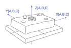

As we have seen, although defined in the Y14.5 2009 Standard and its predecessors as “a set of three mutually perpendicular, intersecting datum planes,” in fact Datum Reference Frames, or DRFs, are actually Cartesian coordinate systems, namely a collection of three mutually perpendicular axes (X,Y and Z), outfitted with linear scales which meet in a point called the origin (XYZ), and form three mutually perpendicular “base planes” (XY, YZ and ZX). DRFs serve only two purposes, namely with the help of Basic dimensions:
to orient and locate the tolerance zones defined by Geometry Control Tools such as Position, Parallelism, Surface Profile, and to orient and locate Datum Targets.
Focusing on item 1, the first purpose of a frame of reference is to clearly specify the mutual orientations and locations of the various features of a part relative to one another. If, in addition, the Datum Features which define the DRFs of two mating parts mate with each other during an assembly process, their DRFs will also coincide, and if their DRFs coincide, a one-to-one relationship between their remaining features will also be established.
Example: If the planar surface on top of an engine block and the two vertical pins sticking out at either end serve to establish the DRF relative to which its cylinders are controlled, and also engage the mating planar surface and two vertical bores in the cylinder head which define its DRF, the relationship between the features of the cylinder head and those of the engine block is automatically guaranteed.
Once we have selected the Datum Features on a part and referenced them in a Feature Control Frame, we have produced a set of instructions for establishing a DRF. Now let’s list the six steps that enable us to construct the DRF, based on the many careful definitions provided in my previous two columns. Here they are:
Decode the Feature Control Frame.
Identify the Datum Features.
Construct the Datum Feature Simulators.
Extract the Datums from the Simulators.
Use the Datums to constrain a “starter” coordinate system in the Simulators, thereby turning it into the DRF.
“Marry” the Datum Features to their Simulators to transfer the DRF to the actual part.
These are the steps that capable coordinate metrology software systems follow automatically without the need for physical simulators, namely by simulating them mathematically. But these steps are not enough. We also need two sets of rules to manage the process, first the rules of “natural DRF establishment” and then the rules of “Datum Feature Simulator management.” Here are the GD&T rule sets extracted from the Y14.5 2009 Standard and refined:

Rules of Natural DRF Establishment
Rule of Datum Feature Precedence (Y14.5M 2009 §4.10 p.58): Datum Features shall be used in the order in which they appear in the defining Feature Control Frame, reading from left to right.Rule of Degrees of Constraint Precedence (a “natural” law): Each Datum Feature must first attempt to constrain pitch and yaw, then roll, and only then, any remaining degrees of translational freedom.
Rule of Non-Override (Y14.5M 2009 §4.10 p.58): No Datum Feature may override degrees of freedom partially or wholly constrained by higher precedence Datum Features.
The Can-May-Must Rule (Rule of Maximum Utilization) (Y14.5M 2009 §4.10 p.58): If a Datum Feature can (is able to) and may (is permitted to) constrain a degree of freedom, it must.
Rule of Composite Datum Feature Utilization (Y14.5M 2009 §4.12 p.65): The individual features of a Composite Datum Feature shall act as a group to constrain those rotational and translational degrees of freedom which they can and may.

Rules of Datum Feature Simulator Management
Rule of DFS Form Control: All Datum Feature Simulators shall have “perfect” form.Rule of DFS Orientation Control: All Datum Feature Simulators shall be “perfectly” oriented relative to one another by the Basic angles of their associated Datum Features.
Rules of DFS Size (Boundary) Control: In the presence of the Tolerance Zone Mobility (Material Boundary) modifier (S) the DFS shall expand toward the in-space surface of the associated Datum Feature and achieve stability relative to it. In the presence of the modifier (M) the DFS shall be fixed at the Virtual Maximum Material boundary and in the presence of the modifier (L) at the Virtual Least Material Boundary of the Datum Feature, enabling residual in-space (M) or in-material (L) mobility relative to it.
Rules of DFS Location Control: Non-planar Datum Features: In the absence of the Translation modifier