Learn more about ultrasonic testing and phased array technology.
Ultrasonics continues to be a growing field for both inspection and medical applications because of advantages that include high sensitivity and ease of use. Relatively new phased array technology is replacing conventional ultrasonics in many applications because of its versatility and capability for high-resolution imaging.
Ultrasonic nondestructive evaluation (NDE) makes use of mechanical waves induced by vibration that propagate through solids, liquids and gases without causing any permanent deformation. At an elemental level, most engineering materials can be envisioned as small masses or particles connected by elastic springs. For any particular particle, vibration exerts a force that displaces the particle, which in turn exerts forces on all neighboring particles. At the same time, the restoring forces of the springs act to return the particle to its equilibrium position. The resulting oscillatory motion of the particles propagates the disturbance (the wave) through the material. Examples of elastic waves include sound traveling through air, earthquake-triggered waves that travel through the earth and waves on the surface of a body of water caused by a rock dropped onto the surface.
The way in which particles oscillate in response to vibration defines different types of waves, called modes. There are two basic modes of mechanical waves that propagate in bulk materials.
For longitudinal waves, also called compression waves, particle motion is in the same direction as the propagating wave. Imagine holding one end of a Slinky fixed while compressing and stretching the other end to generate a wave that travels down the Slinky.
For transverse waves, also called shear waves, particle motion is perpendicular to the direction of wave propagation. Imagine holding one end of a Slinky fixed while wiggling the other end back and forth perpendicular to the axis of the Slinky.
Elastic waves also can propagate as surface waves and plate waves in thin materials. NDE uses all of these different types of waves depending on the material, specimen geometry, material thickness and defects of concern for the test specimen undergoing inspection.
In addition to the wave mode, waves are characterized by their velocity, wavelength and frequency. The velocity of the waves depends on the density of the medium and its elastic properties. The wavelength is the travel distance for one complete cycle, such as peak-to-peak distance. The reciprocal of wavelength is frequency, which has units of hertz, or cycles per second. One of the most important considerations in choosing an ultrasonic probe is specifying the correct frequency, which depends on the material and its thickness, and on the size of defects that must be detected and characterized.
Audible sound for humans is generally in the range between 20 and 20,000 hertz (20 kilohertz). Ultrasonic describes frequencies that are above those of audible sound. Frequencies used to inspect engineering materials including metals and composites are generally in the ultrasonic range of 1 to 20 megahertz, whereas lower frequencies in the kilohertz range are used to inspect materials such as concrete and wood.
Ultrasonic Systems
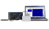
The equipment required for ultrasonic inspection consists of a pulser/receiver, an ultrasonic probe (transducer), and a computer or oscilloscope to display the signals. The active elements of most ultrasonic probes are piezoelectric ceramics. When an electric field is applied across a piezoelectric material it changes shape, thereby inducing a mechanical wave in the medium contacting the probe. In this way, ultrasonic probes convert the high-voltage electrical pulses from the pulser into high-frequency ultrasonic energy (mechanical vibration). The thickness of the piezoelectric element determines the wavelength, and hence the frequency, of the waves generated.
Ultrasonic waves do not propagate well in air so an acoustic-coupling agent is usually used between the probe and the test specimen. Sometimes ultrasonic inspections are performed with the specimen immersed in a water tank, and in this case, the water provides the coupling. When measurements are made in contact mode, a thin layer of water or ultrasonic gel is typically used as the couplant.
Conventional ultrasonics is performed with a single-element transducer. The waves generated in the test specimen diverge radially as they propagate away from the probe through the material. Lenses are sometimes used to focus the acoustic beam at a particular depth-to improve resolution at that depth-and wedges are used to steer the beam.
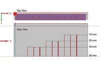
In contrast, phased array probes are composed of multiple piezoelectric elements that can transmit and receive independently at different times. To focus the ultrasonic beam, time delays are applied to the elements to create constructive interference of the wavefronts, allowing the energy to be focused at any depth in the test specimen. The probe’s elements can be arranged in a wide variety of configurations from linear arrays to annular and matrix designs. A recent development is the advent of flexible probes that conform to the geometry of the test specimen.
Ultrasonic Inspection
Material heterogeneity; specimen geometry and thickness; anisotropy; the size, shape and orientation of defects; and material attenuation are among the factors that must be considered in optimizing an inspection strategy.
Attenuation is the term used to describe the energy that is lost as the wave propagates, which is the result of absorption and scattering. Attenuation is material and frequency dependent.
Three common inspection techniques are pulse echo, pitch catch and through transmission. For pulse-echo measurements, the same probe transmits and receives the waves. Reflections, or echoes, are used to detect defects. Ultrasonic waves are reflected at interfaces when there is a difference in acoustic impedance between the materials on either side of the boundary. The greater the impedance mismatch, the greater the proportion of incident energy that will be reflected rather than transmitted across the interface. Voids, inclusions and cracks also can result in reflections, depending on the acoustic wavelength relative to the size of the defects.
Pitch catch describes inspections performed using two probes: one probe transmits and the second receives the signals that reflect off the back wall of the test specimen. The beams are often angled, either using wedges or phased array probes. Pitch catch is particularly well suited to inspecting vertical interfaces such as butt welds.
For through-transmission measurements, one probe transmits and a second probe on the opposite side of the test specimen receives the signals. The advantage is that the waves have a shorter travel path than for pulse echo and pitch catch, and thus less attenuation. This method is therefore particularly useful for thick specimens, but two-sided access is required.
Phased Array Inspection
Phased arrays allow a broad spectrum of inspection strategies that can improve performance, with flexibility derived from the ability to perform electronic focusing, beam steering and scanning. Because thousands of signals are captured and displayed at once, very high-resolution images can be obtained in near real time, and the struggle that operators often have in locating and visualizing defects on the screen is reduced. At the same time, the ability to perform electronic scanning can reduce inspection times by eliminating or reducing the need to move the probe. The most advanced phased array systems include tools such as dynamic-depth focusing that make it possible to achieve consistent resolution throughout the test specimen without increasing the inspection time.
The extensive capabilities of phased array systems improve inspectability and resolution for many nondestructive inspection applications, but they also make it more challenging for operators to design their probe and determine controller requirements. Therefore, modeling and simulation tools are useful for both specifying hardware and determining optimal inspection strategies.


