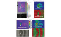
The handheld device shows subsurface defects that cannot be seen visually. The operator simply places a probe against the aircraft structure and with proper equipment setup, subsurface defects appear on a handheld monitor in real time. Source: Imperium
Ultrasound is arguably one of the best nondestructive methods for finding internal defects within composites. However, current single point ultrasonics is a slow laborious process that requires a highly trained specialist. Accidental impact damage cannot easily be found and quantified without complicated equipment that requires extensive training. A quick and easy inspection of aircraft composites in the field is badly needed. Through an ongoing project with Boeing, an ultrasound camera has been developed for in-service nondestructive testing (NDT) of composites that alleviate these limitations. The ultrasound camera is based on a patented imaging array that generates real-time ultrasound images over an area, similar to a conventional camcorder. A non-specialized technician can easily understand the resulting imagery.
The field-portable, simple handheld ultrasound imaging camera is meant as a first line of defense to finding internal composite damage in aircraft structures. Bell Helicopter and Boeing were part of the team on much of this work.
The system is essentially a camcorder for ultrasound. The quality of the information imparted by this real-time video image is far superior to that of conventional A-scan amplitude data or phased array ultrasonics. The images are easy to read and have greater spatial resolution than conventional systems. Integration of ultrasound energy over the time period of a video frame results in high signal to noise and sensitivity.
Industry Needs
Advanced composite materials being used on newer platforms such as the V-22 and Joint Strike Fighter are obviously subjected to harsh conditions. The most prevalent scenario involves the material being impacted during the course of normal use. However, there is no reliable, simple device for large area composite inspection. This damage often cannot be seen from the surface, making visual detection nearly impossible. This damage can have catastrophic results if not found before flight.Currently, the technique of choice is tap testing or visual inspection. If NDT tools are used, the most common is a standard UT probe providing pulse echo ultrasonic waveform data. The returning echo from the original ultrasonic pulse is digitized and processed electronically to provide information regarding the composite. Potential problems with the structure are identified with loss of back-wall echo and can be further characterized by reviewing the entire ultrasonic waveform data. This inspection is performed several times at the factory and during in-service use.
The system can be used by a non-specialist as a quick, simple alternative to tap testing. It was designed specifically for the evaluation of hidden structures and materials, and has proven its capability to detect materials defects, composite delaminations, thermal and mechanical damage.
The subsurface imagery generated by the C-scan ultrasound laboratory system is striking for its video appearance. The imagery appears qualitatively similar to that obtained with visible light cameras. The camera head is connected to a base control unit that contains electronics and a single board computer (SBC) to control the camera and chip. The control unit is controlled by a graphical user interface with a touch screen.
To operate, the technician places the probe against the target. A small amount of ultrasound gel is placed on the area to be imaged to allow the ultrasound to propagate from the probe into the target and begins imaging immediately. An image capture button on the camera probe stores up to hundreds of images before a download is required.
One future consideration is to put a wireless transmitter in the control unit so that images could be sent to a base station or another operator in real time. The software on the touch screen controls the camera and displays video. The interface shows both the C-scan and the A-scan. It shows the C-scan on the left with a crosshair, and the right side shows a full waveform that is the A-scan at the C-scan crosshairs. The A-scan has full flaw detector capabilities, including material velocities, gates and alarms.

The ultrasound camera is based on a patented imaging array that generates real-time ultrasound images over an area, similar to a conventional camcorder. Source: Imperium
Results
Several industry partners have investigated the use of the ultrasound technology for composite damage. For a period of three months, the system was evaluated for the inspection of barely visible impact damage (BVID) for Boeing. Dr. Gary Georgeson of Boeing provided samples for the study. The ultrasound camera was reviewed for both detection capability as well as ease of use.Because porosity is difficult to simulate, the system was evaluated with a real-life example resulting from positive air pressure under the bag during cure of a production part. When a sample image of the porosity is shown, the porous areas are clearly visible.
Dr. Richard Bossi of Boeing writes that the ultrasound camera “has the characteristics necessary to be successful” and “…In particular it has been shown to be very easy to use and fast…”
Based on these results, Boeing has endorsed this program.
Boeing Wireless Program
The quality of these results has led to a program funded by Boeing to transition the camera to airport loading gates for quick inspection of composites on commercial aircraft, for internal defect detection by a non-specialized technician.During 2008, Boeing decided to write a new procedure for the ultrasound camera into its inspection procedures. The images are monitored in real time via a local wireless network by an expert often thousands of miles away. The project, which has been developed in collaboration with Boeing engineers, will allow maintenance personnel to use the device to quickly survey damage without having to bring in harder-to-set-up, conventional ultrasound equipment-all from remote locations.
