Given that GD&T is a symbolic language with which to research, refine and ultimately “encode” the functions of each feature of a machine part, and having provided precise definitions of Datums, Datum Features, Datum Feature Simulators, and the Datum Reference Frame establishment process in earlier columns, it’s time to address best practices for selecting Datum Features and for specifying the order in which they are listed in Feature Control Frames. Failure to get it right in this regard makes even syntactically correct GD&T useless, if not dangerous. Whether GD&T is functional or merely decorative heavily depends on the validity of these choices.
The Datum Feature Selection Process: Because Datum Features serve to constrain degrees of freedom and establish coordinate systems relative to which the remaining features of a part are to be oriented and located, they ought in general (but with some exceptions) to be those features which actually constrain it relative to the mating part during an assembly process. Namely at the end of that process, the objective is for the coordinate systems of two mating parts to coincide in order to guarantee functional relationships between their remaining features. In the examples that follow, this will be the first order of business.
Exceptions: If all the mating parts for a large part are small, no mating feature on the large part can be an adequate Datum Feature to manage its geometry. In this case “reliable” takes the place of “mating” as the selection criterion.
The Datum Feature Sequencing Process: Once the “mating” or “reliable” features have been designated as Datum Features, the order of their importance must be researched. As made clear by our Rule of Degrees of Constraint Precedence found in the Rules of Natural DRF Establishment quoted in our August column, the most important degrees of freedom are pitch and yaw. As a result, with only one exception in the 3-D world, the most important feature of a part is always the one that constrains pitch and yaw during the assembly process. The only exception is the case in which a sphere is the most important feature—for example in an artificial hip—which can only constrain three degrees of translational freedom. In many cases the second most important Datum Feature is the one which constrains the next most important degree of freedom, namely roll. But there are situations in which roll can and even must wait to be constrained by a third Datum Feature relative to an interim DRF established by the first two. The following examples will shed practical light on some of these concepts.
The Tolerance Zone Mobility (TZM) Modifier Selection Process: Once we have selected the Datum Features, determined their order of importance, and given them the appropriate names: A, B and C (never I, O or Q according to the Y14.5 Standard, and never X,Y or Z, which should be reserved exclusively to label DRF axes), the next job is to encode their actual or intended functions using the TZM modifiers (S), (M) and (L), namely (S) to encode the centering or aiming function, (M) to encode the clearance function, and (L) to encode the interference or overlap function.
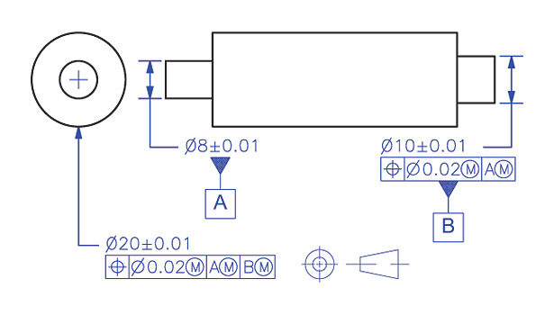
Example 1
Datum Features A and B, set forth in Figure 1, represent two short bearing surfaces of different diameters at opposite ends of a roller, which, in turn, needs to be coaxial with the axis they establish. We see here that the right hand bearing labeled Datum Feature B, is controlled relative to the left hand bearing labeled Datum Feature A, and that the roller is controlled relative to a DRF (Datum Reference Frame) established using Datum Features A and B sequentially. Is there anything wrong here? In fact, everything is wrong.
First of all, controlling B relative to A does not represent the manner in which they will actually function, namely one is not more important than the other; they are both equally important. Second, controlling B relative to A will easily lead to rejection of perfectly functional parts in a coordinate measuring machine evaluation process due to the extreme aspect ratio problem they suffer, namely the short length of A compared to the large distance between A and B. Third, listing the Datum Features sequentially makes B totally nonfunctional, because, based on our Rule of Non-Override, B may only constrain those degrees of freedom which A has not already constrained, but B can only constrain the very same degrees of freedom as A. Fourth, using the TZS (Tolerance Zone Size) modifier (M) in the Position Feature Control Frames for Datum Feature B and for the roller is in conflict with their functions. They serve “centering,” not “clearance” functions. Fifth, applying TZM (Tolerance Zone Mobility) modifiers (M) to A and B, perhaps to please the machine shop, is in direct conflict with their actual function. Although they must of course clear the bearings into which they will be inserted, the primary objective of their relationship with their mating bores is “stability” and “centering,” not “mobility” and “clearance.” It is also important to remember that the TZM modifier (M) encourages the machine shop to aim for the least material boundary of a Datum Feature, exactly what we don’t want in this case. As a result, the code applied in Figure 1 must be scrapped immediately.
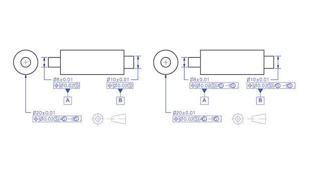
Example 2
As opposed to the code applied in Figure 1, both sets of code in Figure 2 turn Datum Features A and B into a simultaneous set, encoding the fact that they are mutually dependent and act together to locate the roller. In the drawing on the left in Figure 2, Datum Features A and B make up a simultaneous set by default: they are both referenced to the same “super mobile” DRF. In the drawing on the right in Figure 2, Datum Features A and B are made an explicit simultaneous set by referencing them to themselves as a composite Datum Feature “A-B.” Referencing A and B as a composite Datum Feature in the Position Feature Control Frame for the roller also encodes their combined effect during assembly and operation, and, in contrast with the tack taken in Example 1, enables B to actually make its contribution instead of being left out of the game. Furthermore, the TZS modifier (S) found in all Feature Control Frames in Example 2 encodes the “centering” functions of all three features, and the TZM modifiers (S) associated with Datum Features A and B refine the encoding of their combined functions, namely they serve to locate and center the roller. As said before, we continue to use the RMB modifier (S) explicitly in spite of its disappearance in the Y14.5 2009 Standard because of the clarity it enables.
Example 3
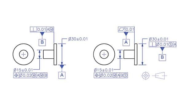
For a final example among countless additional ones we’ll have to ignore, the drawings on the left and right in Figure 3 show two different approaches to encoding the functions of a thin disc whose periphery and one planar surface will serve to orient and locate a protruding shaft to guarantee clearance with a bore in a mating part. In the solution on the left we see 1) that the thin periphery of the disc is labeled Datum Feature A, 2) that the planar surface is labeled B, 3) that B is controlled relative to A as it should be, and 4) that B follows A in the Position Feature Control Frame for the shaft, which seems logical. However, although Datum Features A and B are in fact the acting Datum Features, B is much more important than A, because even though the periphery of the disc has been assigned the job of constraining pitch and yaw, the extremely poor aspect ratio of its thickness to its diameter will ensure that B will win the battle hands down. Furthermore, because A has been made responsible for constraining pitch and yaw by being referenced first in the Position Feature Control Frame for the shaft, B is not permitted to do so and is therefore useless. As if the code in the drawing on the left is not useless enough, referencing Datum Feature A at it Virtual MMB instead of RMB is equally nonsensical, because A serves a centering or aiming function. Turning to the drawing on the right, we see that the Datum Feature labels have been reversed and now represent the actual functions of their features, and that B has been referenced RMB in perfect line with its function.
The Next Workshop
Having dealt with a host of fundamental concepts, rules and processes, our next workshop will be a GD&T skills quiz, followed in the final column for the year by answers and explanations.
Please send us feedback for future topics of interest. I am wondering how we are doing. If there are concerns or comments, please let us know.
Bill Tandler is the president and chief technical officer of Multi Metrics Inc. (Menlo Park, CA). He can be reached at [email protected] or (650) 328-0200.