|
Read on to learn more about... |
A key aspect of surface texture is that it consists not just of random roughness but of many spatial wavelengths, or the peak-to-peak spacing along the profile or across the surface. The predomination of some wavelengths over others will determine, to a large extent, whether a surface will glide or stick, retain lubricant or run dry, squeak or leak.
To ensure that a surface will perform its intended functions, one must determine the optimum composition of spatial wavelengths in its texture for the particular application, and then specify those wavelengths appropriately. The process of measuring the texture must also be well specified and controlled in order to obtain reliable data.
This article will discuss factors which impact texture measurements, and methods and guidelines for controlling them in order to produce reliable surface roughness measurement results.
Measuring Spatial Wavelengths in Surface Texture
For many engineers, setting the quality of a surface’s texture means defining a single parameter, such as average roughness (Ra). However, Ra is just the beginning of the story. Vastly different surfaces may still have the same average roughness. A shot-blasted part with uniform roughness, one with a few very sharp spikes or another with many small divots may pass the same inspection for Ra, but would perform very differently in actual use.
It is therefore important to consider the spatial composition of surface texture as well as the overall roughness amplitude to understand how the surface will function. Three general terms are used to describe spatial wavelengths. “Form” refers to long wavelengths, “waviness” to intermediate wavelengths and “roughness” to short wavelength features. Whether a particular wavelength range is considered form or roughness depends on the surface and its application. For example, spatial wavelengths in the two to 20 millimeter range might be considered waviness on an engine block deck face, whereas this same range might be thought of as roughness when addressing the road texture under a tire.
Texture data can be filtered to emphasize or suppress a particular range of spatial wavelengths. This filtering can be accomplished deliberately by implementing filtering in the measurement software data. It can also happen inadvertently due to mechanical limitations in the measurement system or a poorly controlled testing environment.
Software Filters
Most common measurement systems enable an operator to apply filters to specify the spatial wavelength range to be included in measurement results. There are four common types of filters: long wave, short wave, notch and band pass. The filters let a metrologist subtract out non-critical wavelengths and emphasize those critical to surface function.
The cutoff wavelengths, λc (long wave cutoff) and λs (short wave cutoff), specify the wavelength range to be included in the measurement results. The choice of cutoff wavelengths will greatly impact the measurement. Figure 3 shows a surface profile which has been measured using four different cutoff wavelengths. The average roughness (Ra) value is dramatically different in each case.
Clearly a testing procedure must specify the cutoff wavelengths to ensure meaningful test data that will drive a process in the correct direction. In fact, when specifying a surface texture using parameters such as Ra, the American Society of Mechanical Engineer’s ASME B46.1 standard dictates that the cutoff wavelengths must be specified. The standard also provide guidelines for the metrologist to establish cutoff wavelengths in the case in which none are specified. Note, however, that these guidelines are merely intended to include the dominant features of the surface in the measurement, whether these features are relevant to the function of the surface or not.
Filtering Introduced by the Measurement Method
Several types of instruments are employed to measure surface texture, including optical profilers, stylus profilometers and scanning probe microscopes. Each type of system is capable of measuring a range of spatial wavelengths and amplitudes. These ranges overlap to an extent, so it may be possible to measure a specified parameter using any of several systems. However, each type of system has its own peculiarities and sensitivities. It is therefore preferable to specify the instrument to be used for any given measurement in order to maintain consistent data.
Aspects of the measurement setup may also need to be specified to achieve consistent results. For example, if the surface under test is known to have very directional texture (i.e., a lay), as in the surface of a machine-turned shaft, then the direction of the measurement scan may need to be specified as across the lay to sufficiently characterize the surface. Also, in stylus or scanning probe-based methods, the scan speed will impact how precisely the probe is able to follow the surface, particularly when the surface includes high slopes or steps.
Filtering Induced by the Measurement Probe
The size and shape of the measurement probe will also limit the range of measurable spatial wavelengths. A large radius probe cannot fit into narrow trenches or small pits, thus it mechanically filters out these short wavelength features. Figure 4 shows that a small-radius tip (blue) can track the shorter wavelength features of the surface at higher lateral resolution than can the larger, blunted red stylus. On the other hand, the larger stylus may be able to provide a clearer gauge of waviness by filtering out short wavelength roughness components.
Wear on a probe or tip introduces an additional source of filtering. A worn or broken, small-radius tip will perform more like the red probe in Figure 4 and may produce varying results across time. This aspect of tip wear becomes particularly critical for the very small, fine tips used in scanning probe applications, in which a small amount of wear can mask a wide range of critically-important spatial wavelengths.
Optical profilers can be similarly limited by the numerical aperture of the objective and the resolution of the camera, both of which act to optically filter short spatial wavelengths.
Part Wear as a Filter
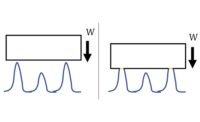
Surfaces that face ongoing, high-load wear, such as engine or drive train components, will change considerably over time. A machined part’s surface will initially contain both short wavelength structures from machining operations as well as deep, well-formed trenches which can facilitate the flow of lubricant. As the surface begins to wear, sharp peaks are ground down and deep valleys filled in with displaced and deposited materials. The spatial wavelength composition of the texture therefore changes continuously as the surface wears.
As a part evolves through a wear process, the various texture parameters such as Ra change as well as the spatial wavelength content. Thus the designer of a surface must consider the differences between the unworn surface typically inspected after production and the actual surface during operation. For example, the measurement of short wavelength components (about one micron) of an unworn surface may not be critical and may mask the measurement of important spatial features in the waviness regime (about two millimeters).
Surface texture measurement has matured well beyond the early days of simply measuring average roughness and a handful of other 2-D parameters.
The ability to specify and assess such aspects of texture as the spatial wavelength composition helps designers and manufacturers to develop parts that will reliably achieve their functional requirements.


