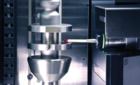
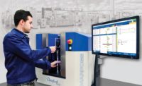
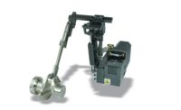
The rapid growth of in-line gaging over the last few years has been focused primarily on the use of this approach as a tool for improving quality. In a typical application an in-line gage is located physically within the cell, line or other system configuration to inspect each individual part and provide both tool-wear compensation (feedback) for the control, and data for SPC, tracking and other purposes.
In this role, the in-line gage is normally loaded and unloaded by the same automation used to transfer the part within the process. The gage, or gages, may be located between operations, used for final inspection, or both, depending on the process.
In most cases, the in-line gages are used as part of a system that includes both in-process gages and off-line gages, coordinate measuring machines (CMMs) or other inspection technologies. Depending on the application, in-line gages may use any of the common gaging technologies including air, contact, laser and optical or a combination of technologies at different points within the manufacturing system. Each technology has unique advantages and application limitations.
Air gages are very tolerant of environmental contaminants and variations in part finish. They also tend to be very economical. This technology is a good solution for parts that cannot be touched.
On the other hand, air gaging, although initially less expensive, has a higher lifetime cost due to the production of compressed air and mist containment when measuring a part that is wet with coolant that can be atomized into the atmosphere when the gage is used. The technology also requires a very small gap between the gage and part which may offer challenges in part loading.
Contact gages are precise, robust, flexible, easy to apply, and offer a wide range of measurement capabilities. They are tolerant of environmental contaminants and variations in part finish. They also have a lower lifetime cost over air gages. However, since they must touch the part, it is possible for contact gages to leave unacceptable marks on highly finished surfaces.
Optical gages are extremely flexible and do not touch the part, making them the preferred solution for certain medical and aerospace components with highly polished surfaces. However, they generally require clean, dry surfaces which can impact their applicability in certain in-line gaging applications.
While this description covers the bulk of common in-line gaging applications, there are many variations on the theme. The gages, for example, can be fully dedicated, flexible, modular or re-toolable, depending on the nature of the application.
Briefly, a flexible gage is one that can inspect a range of part types without having to be reconfigured. A modular gage is made up of standard components such as pencil probes, measuring armsets and work rests mounted on a base that allows mounting details to be randomly located and re-located as necessary to inspect a wider range of parts. A re-toolable gage requires a change of mechanical elements to handle different, but similar, parts.
As noted, the system may use more than one gaging technology. It may also include other functions such as laser marking or pin-stamping, part sorting and classification, and a whole range of data storage and analysis tasks.
What these systems tend to have in common is that they are applied to stable, controlled processes as a quality assurance tool. In-line gaging is a proven performer in that role, and as a result, other potential applications for the technology receive less attention.
Extending the Useful Life of Veteran Equipment
For example, in many cases, adding in-line gaging to an existing manufacturing system can be a low-cost way to extend its useful life. No matter how well maintained, veteran equipment eventually reaches a point at which it becomes less stable, and the process of which it is a part becomes increasingly difficult to control.
Rather than re-build or replace the equipment, it’s often more cost-effective to add an in-line gaging capability to the system and use the virtual real-time feedback it provides to monitor and compensate the individual operations on a part-by-part basis. The compensation capability can help ensure ongoing quality, while the monitoring data can help identify problem processes and machines for remedial action and/or eventual replacement.
Nothing lasts forever, of course, so aging equipment will have to be re-built or replaced eventually. However, that doesn’t necessarily mean that the in-line gages used to extend the useful life of that equipment will also need to be scrapped. By specifying flexible, modular or re-toolable gages initially, it is frequently possible to re-purpose in-line systems for new equipment and even new processes with minimal additional capital investment.
The relative advantages of each system are highly application dependent and should be evaluated with the assistance of the gaging supplier. As a general rule, however, specifying some degree of flexibility, modularity or re-toolability in an in-line gaging system will result in significant long-term cost savings.
An automotive brake disk supplier used this approach in specifying an innovative flexible and re-toolable bench gage to provide 100% in-line inspection capabilities for a family of eight different parts. The parts vary in overall height, braking surface thickness and hat OD.
The gage dynamically measures rotor thickness; thickness variation; lateral runout of the braking surface; pilot bore ID; hat OD; brake surface parallelism; and mounting face flatness. Because it was designed for both flexibility and re-toolability, the gage can be retooled in 15 minutes as opposed to the three to four hours that would be required for a conventional gage.
Increasing Productivity Outside of the Process
In-line does not necessarily mean inside. There are many applications where an in-line gage can be used effectively to increase productivity by measuring parts before they are processed.
It’s often necessary, for example, to locate a part feature in relation to another feature. The traditional solution is to fixture the part in the machine, and then use a gage, probe or some other device to locate the reference feature and communicate the necessary offset to the machine control.
This is all done within the machine cycle, but it doesn’t have to be. Using an in-line gage to locate the reference feature before the part is fixtured moves this operation outside the machine cycle and results in a direct reduction in per-part cycle time. The same principle can be applied to a wide range of operations by using in-line gage data to either locate features, or to pre-position cutting tools or grinding wheels to minimize rapid-traverse to part time within the machining cycle.
A small engine manufacturer adopted this approach for an automated crankshaft bearing grinding operation and cut three to five seconds out of the process cycle time. An initial pilot test using a gage stand proved so successful that the manufacturer re-configured the entire system to optimize the advantage gained by the in-line gaging application.
In-line gaging is a rapidly maturing technology with a broad range of potential applications. While the traditional quality-focused uses of in-line gage systems will undoubtedly continue to predominate, it would be a mistake to overlook the broader applications of this technology to extend the life of capital investments and directly improve process productivity.
|
TECH TIPS
|


