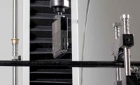
It seems so simple: Place specimen in grips, perform tensile test, and achieve consistent results, right? Not really. Unfortunately, gremlins lurk, all conspiring to introduce errors. The “fishbone diagram” illustrates how errors and variability can occur. Each “rib” of the fishbone is a source group of contributing factors. In particular, we will focus on alignment—why it is important and what to do about it.
In an ideal world, the force applied to the specimen is exactly aligned with the axis of a perfectly straight specimen. So, it is true that any deviation from perfect uniformity of stress in the specimen is a potential cause of variability. (This is particularly true with stiffer, stronger materials and components—where slight misalignments can cause dramatic variations in cross-sectional stress.) Knowing this, the operator must assess the specimen for various factors: Is the tensile specimen axially perfect? Is it uniform—free of curvature in the gage area and cross-section? Was it machined properly—including nicks, scratches and machining marks? Is the “tab” (where the specimen is gripped) flat and parallel to the gage section to ensure that the force is properly concentrated in the desired failure zone? Once the specimen passes inspection, the grips are next on the examination table.
A superior example of why grip alignment is critical can be demonstrated by high-stiffness carbon fiber reinforced plastic (CFRP). This advanced material is used in aerospace and demanding applications where strength and lightweight are paramount. CFRP is about six times stronger than steel when normalized for weight. The material is unique in that it does not yield—it is linearly elastic up to failure, where it literally explodes. Needless to say, aligned grips are essential for accurate results.
The pursuit of uniform stress requires a very precise grip. Most people familiar with mechanical testing will recognize the typical “wedge action grip,” where wedge-shaped jaws are used to clamp the specimen. In order to make the grips as light as possible (user-friendly), they are commonly “open-fronted”—so the specimen can be inserted from the side. However, they are also “closed-back”—the feature which makes the grip body strong and light. As a consequence of this design, it is clear that as the force increases, the grip body deflects—ever so slightly—and grips the specimen harder in the back than in the front. The outcome is a non-uniform stress distribution and a potential contributor to data scatter. For this reason, the preferred grip for advanced materials is symmetrical side to side and front to back (either hydraulic or mechanical).
Note that proper placement of the specimen in the grips is also essential—both front to back and vertically. For this reason, advanced grips provide “specimen stops” to ensure that the specimen is placed in the grips the same way for every test. The stops are adjustable such that the centerline of the specimen can be precisely aligned with the centerline of the grips.
Now that we have a perfect specimen and ideal grips, we can just put them in the system and go, right? Not so fast. Perhaps the single biggest contributor to misalignment in the “load string” (everything between the stationary and moving parts of a testing system) is the mounting and alignment of the actual system. For round specimens, perhaps the best approach is a universal coupling that will pull straight under increasing force. Rigid couplings are acceptable as well but should be checked for alignment and bending. Universal couplings or swivel joints simply do not work well with flat specimens—it is close to impossible to repeatedly clamp a flat specimen in a mechanical wedge grip that is mounted on a swivel coupling. Therefore, to ensure consistency—rigid mounting is recommended for flat specimens.
Let’s say we have a perfect specimen, in ideal grips, mounted properly, in a machine that provides perfect motion. How can we be sure that everything is okay? Increasingly, alignment checks are being required of test labs to prove that conditions are within acceptable limits. Again for composites, NADCAP (the National Aerospace Defense Contractors Accreditation Program) has two standards required of suppliers to critical aerospace manufacturers: AC7101 (General/Metals), and AC7122 (Composite materials). AC7101 states that bending must be less than 10% for static tests, 5% for fatigue tests—AC7122 requires 8% or less. The only way to properly check for bending is by making a strain-gaged specimen that matches the properties of the specimens to be tested; apply 8, 9, or 12 strain gages; and apply roughly 1,000 microstrain. (Reference ASTM D1012, D3039—among others). The calculated bending must be less than that specified in the standard. If it is, you are in great shape. If not, read on.
An alignment verification failure means one of several things, but most likely the following: Either the load string has a bad part (the grips, the mounting) or simply needs to be aligned. Aligning the load string is done in two way: X-Y (lateral) and angular. In the “old days” this was done with shims, hammers, repetitive iteration, and luck. Nowadays, alignment fixtures are available to not only align the load string without loosening anything but to do so under load with real time readout of bending.
So, we are done: the perfect specimen, the ideal grips, mounted properly, in a system that provides perfect motion, in way that produces bending below target limits. Now, we are ready to tackle all the other gremlins lurking in other areas, trying to hurt the consistency of our results!


