|
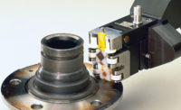
| A robotic eddy current probe inspects an automotive spindle. The pencil type probe follows the spindle’s profile as it rotates. Any flaws in the material generate a signal which indicates a flaw. A part handling robot (not shown) places the part in the spindle and then either accepts or rejects it depending on the test outcome. Source: UniWest |
Although the automation of NDT methods other than eddy current is conceivable, in most cases it is cumbersome at best. The use of consumable materials, such as fluorescent fluids for dye penetrant systems, ferrous sprays for magnetic particle systems, couplant fluids for ultrasound and radioactive materials for X-ray testing, represent additional costs in terms of testing, safety and waste disposal.
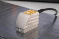
Unique among NDT methods, eddy current testing eliminates the need for any external materials because the EC probe is air-coupled to the part. An eddy current probe can consist of one or more coils, i.e. windings of copper wire. Generally, a primary coil is used to generate a varying magnetic field. A metallic part being inspected with the probe responds by generating internal eddy currents whose field “talks back” to the probe. Any discontinuity in the metal, such as a crack or pore, changes the flow of the eddy currents and hence the “back-talk.” A secondary coil configuration in the probe is then used by the eddy current instrument to sense, measure and display the degree of the “back-talk.” Eddy current testing is a highly sensitive method for detecting small flaws in metals or for sorting metal parts for changes in composition, geometry or other factors.
Robotic eddy current testing systems typically comprise five electro-mechanical components: a part-handling robot, a probe manipulation robot, a part positioning and rotation mechanism, the probe itself and an eddy current signal processor. All these devices communicate and are controlled by a programmable logic controller.
Because eddy current signals are dependent on flaw depth, rather than just length and width, flaw detection tends to be more accurate than other methods which sometimes reject serviceable parts due to inconsequential surface scratches. Eddy current testing defect limits are set by calibrating the instrument to an artificial flaw in a defect-free test part. This artificial flaw is, most commonly, an electrical-discharge-machined (EDM) notch 0.005 inch deep, 0.003 inch wide, and 0.100 inch long. Within the EC instrument, the notch signal serves as the baseline from which the system can be adjusted to greater or lesser tolerances. Any defect generating a signal greater than the calibrated standard is rejected. In a robotic system rejected parts are pulled off line by the part-handling arm.
In addition to the benefits robotics brings to eddy current testing, it also provides the unique ability for the EC system to self-calibrate. To compensate for minor variations in the eddy current signal over time, the part-handling robot can be programmed to periodically place a flaw-free master into the test station to ensure periodic calibration accuracy. The difference between the amplitude of the signal generated by the master and optimal settings for the eddy current instrument is used by the machine controller to make sensitivity adjustments for consistent performance.
Robotic arm inspection paths and points are established by manually running the robot arm through a course while the machine is in learning mode, which produces a permanent motion profile for a given part. A part’s critical inspection points may be identified either by historic performance records or by finite element analysis. Recurring defects can be managed by dividing a part into any number of inspection zones to identify areas in which flaws arise with greater frequency than others. A log of all rejected parts shows the zone in which flaws occurred. Compiled reports of rejected parts enable the identification of product weaknesses and improvement options.
Robotic eddy current testing offers manufacturers a cost effective means of ensuring quality control of safety critical components. By integrating the well-established field of nondestructive testing with the newfound cost-efficiencies of industrial robots and controllers, robotic eddy current testing promises to improve flaw detection at the same time it promotes the increased use of nondestructive testing and the reduced occurrence of in-service failures.
Phil Warga, chief executive officer of robotic NDT system manufacturer, Salem Design and Manufacturing (Salem, OH), sums up the value of robotic eddy current testing: “Today robotics is bringing to nondestructive testing the same versatility and cost-efficiencies that CNC brought to parts production thirty years ago.”


