Detecting product surface flaws—such as discolorations, burns, cracks, and scratches—is a difficult task for human or machine vision. These defects can have random shapes and low contrast, and are often obscured by the product’s natural surface texture or pattern. Detecting these defects with machine vision requires knowing what the defects can look like, careful attention to lighting, camera resolution and part presentation, and sophisticated machine vision algorithms.
Here we discuss cracks and scratches, which have rapid intensity changes that produce high spatial frequencies.
Understand the Task
Knowing how these defects occur gives you some ideas of how the defects will appear in the image. For example, a powdered metal (sintered) part might crack only where the material is thin. This “prior knowledge” can improve flaw detection reliability by limiting the machine vision analysis to areas, structures, and directions where flaws occur.
How is the inspection currently done? If it is done by machine vision, what are the current system’s inadequacies? When machine vision is replacing human inspection, ask the inspectors how they do the task and watch them do it. For example, to detect scratches on smooth plastic, a human inspector might turn the part until the scratch “lights up.”
We detect surface flaws by knowing, intuitively and by training, what these defects look like. For example, scratches often appear as a sequence of straight or gently curved line segments that we subconsciously connect into a line, using our “gestalt” abilities. For machine vision, these abilities must be approximated by vision algorithms.
On difficult inspection tasks, human inspectors’ decisions might disagree—is that a scratch or just some brighter points on the part that happen to line up? This is a warning that reliable flaw detection might not be possible. If the defects are clear and what constitutes a defect is well specified, then machine vision can give more consistent decisions than human vision.
Lighting is especially critical in surface flaw detection because these defects typically have low contrast that proper lighting can amplify. For defects that raise the height of a flat surface, try low angle illumination to “light up” the raised area’s edges. For defects that are flat, or when looking for defects on a curved surface, try diffuse light. As you might know, lighting is somewhat of an art. Ask your lighting vendor or vision integrator for help.
The camera and lens must image at three pixels or more across a crack or scratch. Sometimes multiple cameras or stepping the part are needed to inspect the entire surface of the part with the required resolution. Because we are looking for small defects, it is important that the part surface stay in sharp focus. This can be a challenge when the part surface is curved.
Shading Correction
With clear images of good and defective parts, you are ready to try various machine vision algorithms. Software that includes such algorithms makes it easy to try different solutions and is useful for detecting cracks and scratches.
If the intensity of the scratch or crack is well above or below the part’s natural texture, the detection task seems easy: Apply intensity thresholds to show only the pixels from the scratch or crack, and the count of these pixels is your defect signal.
However, pixel values outside the thresholds might be due to non-uniform illumination, rather than a scratch or crack. Shading correction removes variations in illumination, and so improves crack and scratch detection. Shading correction is typically done by spatial-frequency filtering or by dividing the input image by a reference image.
A spatial high-pass filter amplifies high spatial frequency cracks and scratches and removes low frequency changes due to variations in lighting intensity. This filter can crack and scratch detection. Unfortunately it also amplifies the part’s surface texture, giving a noisy image that might make scratch or crack detection difficult.
Instead of amplifying high spatial frequencies, we can subtract low spatial frequencies. First make a low-pass (blurred) image from the input image by averaging pixel intensities around each pixel. These local averages approximate the slowly-changing light intensity. Next, subtract the low-passed image from the input image, leaving high spatial frequency changes—scratches and cracks—against a nearly flat intensity background.
A reference image is created by temporally averaging a sequence of images without the part in place. The reference image shows the illumination distribution. Subsequent input images are divided by the reference image to remove the effects of illumination. Because image intensity is the product of the illumination and the part’s reflectance or transmission, pixel-by-pixel division by the reference image cancels the illumination factor leaving only the part’s reflectance or transmission. This method is commonly used in microscopy but less so on production lines.
Golden Reference Methods
Most parts have reflectance or transmission variations that can obscure scratches and cracks. We can extend the reference image idea by averaging precisely aligned images of known good parts, instead of empty images, to produce a golden reference image. The ensemble variance gives an estimate of the natural or acceptable variation at each point on the part.
This golden reference is subtracted from or divides input part images to remove both lighting variation and part reflectance or transmission variations. The variance measure is used to set detection thresholds at each point in the image. This method works well when the part intensity structure is very closely controlled, for example with semiconductors. The golden reference image and the part input image must also be precisely aligned in position, rotation, and scale.
Repetitive Pattern Removal by Matched Filters
Golden reference methods can sometimes remove repetitive part patterns, such as meshes or grids. However, golden methods give false alarms if the parts are not closely controlled in structure and reflectivity or transmission. In these cases, a matched filter might give better results.
The basic idea is to build a filter that matches the spatial frequency components of the part’s repetitive pattern, and then apply that filter to filter out the pattern, leaving the surface flaws mostly intact—optimizes the signal to noise ratio for the surface flaws. The advantages of using matched filter include some tolerance to alignment mismatches between the filter and the input image and, with normalization, tolerance to pattern intensity changes.
A known good image of the repetitive pattern is transformed into spatial frequency space using a fast Fourier transform (FFT) to make the matched filter. The FFT is then applied to input part images. Now in the spatial frequency domain, we divide the input image by the matched filter, effectively removing the spatial frequencies in the input image that match the matched filter’s frequencies. If we don’t care about the position and structure of the surface flaws, then the flaws can sometimes be detected in the spatial frequency domain. Or we use an inverse FFT to construct a spatial intensity image without the repetitive pattern’s structure and do the detection in the spatial domain.
If spatial frequencies in the flaws overlap those in the filter, the flaw will be partially erased. If there is enough overlap, the filtered signal won’t be strong enough to provide reliable flaw detection.
Structural Methods
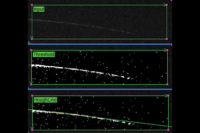
Even after using the above methods, the flaw signal is often still too weak for reliable detection. Structural methods use prior knowledge of the structure of flaws to improve detection. For example, scratches appear in the image as points approximately in a line. By amplifying or accumulating points along a line, we can improve detection reliability for this type of flaw. Here are two of the many structural methods.
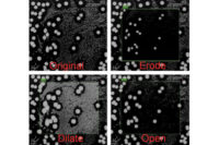
Mathematical morphology modifies and detects shapes (morphology) in the image. The erosion operation “peels off” pixels from bright objects’ edges. The dilation operation adds pixels to a bright object. Assume a scratch is brighter than the object it is on and that we know the approximate direction of the scratch. Then using directional dilation we can extend and “fatten” the points in the scratch so that they touch. Then directional erosion can, optionally, “thin” the resulting line, to also reduce noise pixels that were “fattened.” There are many other morphological operators that can be applied to improve flaw detection, assuming you know something about the flaw structure in advance.
In the Hough transform, each pixel above threshold “votes” for all possible lines it could be a part of. Possible lines with enough votes (above a threshold) indicate lines of pixels in the image that are scratches or cracks. Hough methods are able to detect very weak line signals because they integrate the evidence for a line over many pixels. They work very well in some situations but are often slow or too difficult to set up.
Every new surface flaw is a challenge but, with experience and the right tools, one that can be met. In this overview of methods I’ve, dare I say, only scratched the surface of this topic. V&S
References
http://en.wikipedia.org/wiki/Gestalt_psychology
http://www.mif.vu.lt/atpazinimas/dip/FIP/fip-Shading-2.html
“Image Morphology” by Ben Dawson, in July Vision and Sensors
http://www.qualitymag.com/articles/91228-image-morphology
http://en.wikipedia.org/wiki/Hough_transform
Ben Dawson is with Teledyne DALSA
Industrial Products, Inc.
(978) 670-2050


