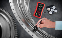
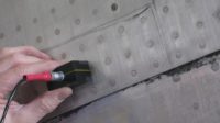
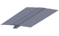
Nondestructive testing (NDT) of aircraft is essential to the continued safety of passengers. This article looks to explore how eddy current testing (ECT) can be effectively used to help in improving the long term reliability of aircraft by the detection of defects before they become critical, exploring ECT theory, how it can be applied to aircraft and the key elements of this NDT technique that separate it from other methods.
On a day-to-day basis ECT play a vital role within any aerospace maintenance and repair organization (MRO) and as the number of planes and passengers increase as will the average aircraft age, so must the amount of NDT being carried out on aircraft across the world. The following extracts from leading worldwide authorities give a clear idea of just how important NDT in aerospace is.
According to the Federal Aviation Authority (FAA) Aerospace Forecast (fiscal years 2013-2033), the total passenger traffic between the United States and the rest of the world was estimated in 2013 to be up by 2.6% on the 2012 figure of 171.8 million passengers. They go on to say that this “accelerates in 2014 (up 4.5%) as the world economic recovery solidifies. For the balance of the forecast period, stable worldwide economic growth leads international passengers to grow at an average rate of 4.1% a year, totalling 402.9 million in 2033.”
The Deloitte Global Aerospace and Defence Industry Outlook 2014 report again cemented the views of the FAA report by predicting, “Revenue growth in the 5% range is expected for the overall Aerospace and Defence (A&D) industry in 2014.”
However it went on to comment that “Global revenues for defence companies are on a downward trend. Global defence spending is declining; resulting mainly from reduced armed conflict in Iraq and Afghanistan and affordability concerns in many traditional militarily active governments. However, defence spending is increasing in several areas of the globe, especially in the Middle East, India, China, Russia, South Korea, Brazil, and Japan.”
With hundreds of millions of passengers expected to take to the skies this year alone, it is clear why NDT is so important to the smooth and safe running of the aerospace industry. When looking at how ECT plays its part in the cycle, it is helpful to have an understanding of the theory behind eddy current testing.
Theory of Eddy Current Testing
ECT is often given bad press as being difficult to understand and too complex for the average NDT inspector. However it is based on one of the most primary scientific principles, electromagnetic induction.
Electromagnetic induction is the principle that enables electricity to be a useful power source such as in an electrical generator. “Electromagnetic” describes how electricity and magnetism interact to produce electricity. “Induction” is the process by which a varying magnetized field induces an electric current in a conductor.
Eddy current testing uses this principle to detect flaws in conductive materials. An excitation coil carrying current is placed close to the component to be inspected. The alternating current in the coil generates a changing magnetic field, which interacts with the component and generates eddy currents.
Variations are monitored either using a second coil, or by measuring changes to the current flowing in the excitation coil. The presence of any flaw will cause a change in the phase and magnitude of the eddy current field and therefore a change in the phase and amplitude of the measured sigal.
Advantages & Disadvantages of ECT
At this stage it is important to lay out some of the positives and negatives that ECT offers. This way we can begin to look at the application within aerospace that ECT can be used in from a fair and balanced point of view.
Advantages:
- Sensitive to small discontinuities at right angles to the surface (e.g. cracks and corrosion)
- Not affected by non-conductive layers (e.g. paint and sealant)
- Good for surface and near surface Inspection in thin (up to 6mm thick) non-ferrous material.
- Immediate results
- Equipment is very portable
- Method can be used for much more than flaw detection (e.g. sorting heat treatment or materials coating measurement)
- Minimum part preparation is required
- Test probes do not need to contact the part
- Suitable for complex shapes
- Small size of the sensor allows probes to made to inspect poor access areas (e.g. grooves and thread forms) and difficult access areas (e.g. inside an engine and blade trailing edges)
Disadvantages:
- Only conductive materials can be inspected
- Surface must be accessible to the probe
- Surface finish and roughness may cause problems
- Reference standards needed for setup
- Depth of penetration is limited
- Flaws such as delaminations that lie parallel to the probe coil winding and probe scan direction are undetectable
Eddy Current Testing On Aircraft
When using NDT on an aircraft, there are many areas of the plane that can be inspected using eddy current testing and all fall into one of the following categories:
- Defect detection including surface and sub-surface crack detection using single and dual frequency
- Material sorting of ferrous and non-ferrous metals and coating and wall thickness assessment
- Hole inspection manually and dynamically
- Wheel inspection
- Corrosion detection in multi-layer structures
However this is not to say that other NDT methods cannot be used; in Figure 1 we have highlighted these, but have set out their limitations in comparison to ECT.
The Main Principles of Performing an Eddy Current Inspection
Within ECT there are three main parameters to understand in an eddy current test: frequency, phase and gain.
Frequency:
Frequency describes the rate at which an alternating current (usually a sine wave) changes direction. The number of times per second a cycle occurs is called the frequency and the units for these are measured in Hertz.
In terms of eddy current testing, frequency is one factor in determining how deep an eddy current signal can penetrate the material. Choosing the correct test frequency is affected by the type, size and frequency of probe, the depth of penetration required in your inspection area and the conductivity value of the material you are inspecting (Figure 2).
As a rule of thumb, a higher frequency will increase the resolution on near surface defects and also the phase separation of those defects, but does limit the depth of penetration. However choosing a lower test frequency will increase the depth of penetration, but this will reduce the phase separation as the depth increases.
In general, the effective depth of penetration using eddy current inspection is classed as the top 37% of the materials thickness before the signal amplitude reduces and the phase lag increases making the test less reliable.
With this in mind, it can be useful to use more than one frequency to improve the discrimination of a test.
Phase:
In simple terms, changing the phase rotates what is seen on the screen. This is useful because the eddy current “spot” on the screen moves in different directions according to what is happening beneath the probe.
Usually we are only interested in looking for a defect. We don’t want to confuse a defect signal with that of “lift-off,” which is a signal caused by the probe “lifting” away from the surface of the material being tested. Fortunately these two signals move the spot in different directions.
To help identify the difference between these two signals we can create the “lift-off” signal by repeatedly lifting the probe on and off the material, then by changing the “phase” the signal can be rotated until it moves in a horizontal direction to the left of center (Figure 3 and 4).
So when performing a test any signal going horizontally can easily be ignored and any signal going away from the horizontal is an indication that something has been detected, possibly a defect.
Gain:
Gain can be thought of as zoom and increases the size of the signals on the screen. Ideally the gain should be set so that the size of defect that you are looking for fits to about 80% of the screen height. To do this you will need a test block with a defect of a known size on it so that you can adjust the gain settings accordingly (Figure 5 and 6).
One concern is that if the input amplifier gain or signal drive level is too high you may “saturate” the instrument, which overloads the instrument circuitry and thus prevents a signal being displayed.
Monitoring Crack Growth & the Early Detection of Flaws Before They Become Critical
As well as NDT inspections, periodically monitoring possible crack prone areas before a defect appears can significantly help in extending an aircraft’s life.
The main cause of possible cracks emerging is the cyclic fatigue that the structure is subject to during operations. Stress engineers work out how much fatigue damage the structure can tolerate before problems possibly occur. This is achieved by carrying out material or component tests on test rigs or indeed on full structures that are subject to varying stress loads in a controlled environment.
These tests allow the engineers to see how much stress a component will take over a certain period, i.e. until it breaks. From this point they also work out the critical crack size, i.e. the point when the component will break or fail. Inspections are carried out before the critical crack length is reached, theoretically at least.
A procedure is written and entered into the service schedule for that component/aircraft so that a small crack can be detected long before it gets to a critical size. The procedure will include a test piece to verify the correct calibration of the test system and ensure that the required defect detection threshold is achieved before, during and after the test.
If a crack is detected before the airplane is scheduled for routine maintenance sometimes this crack will be monitored for growth to ensure it does not reach a critical size or start to grow at an increased rate.
However, there are times when cracks are found and need to be repaired immediately. On commercial aircraft this is not the norm, but on military aircraft immediate remedial action is standard due to the abnormal stress that structure could be subjected to during operation.
Conclusion
Consistently monitoring cracks for advances in their growth is important to maintaining aircraft safety. Eddy current inspection can be used to achieve this. Ideal for surface defects, ECT offers the aerospace industry a clean testing method that is ideal for thinner metal materials—the exact types that many aircraft are made of.
If conducted correctly and with the right level of training, eddy current testing can be a fast and cost effective inspection tool.


