An important element in ensuring the quality of finished parts is nondestructive testing (NDT). NDT is the inspection of material or parts without impairing their future usefulness.
Every NDT method involves putting some kind of energy into the test material, and observing how that energy is affected by the part. In general, defects affect the energy differently than good material.
The most commonly used NDT methods are:
- Liquid Penetrant Testing
- Magnetic Particle Testing
- Ultrasonic Testing
- Radiographic Testing
After any of these methods are performed, there is generally no way to confirm that a specific piece of material was tested. The test documentation is the only real evidence. A common saying in NDT is, “If it isn’t documented, it never happened.”
Therefore, maintaining the link between the parts, the identifying documentation which accompanies them, and the testing they received, is extremely important to the manufacturer and to the end user. This link is called traceability. You can often re-inspect a part, but there’s no way to restore lost traceability.
We will go through four separate inspection processes and see how traceability is maintained during each.
Liquid Penetrant Inspection
Liquid penetrant inspection (often called LP, LPI, or PT) finds defects which are open to the surface, like cracks and porosity. The penetrant, which is light oil containing a dye, is applied and allowed to soak in to defects. The excess is removed with water or solvent. Developing powder is applied, and the penetrant bleeds out and appears as an indication.
After the material container is opened, the technician confirms that the contents of the box, including any heat and lot numbers, match the job traveler created from the purchase order received. For instance, if the paperwork states 40 pieces of hex bolts were submitted for LP, but the box actually contains 40 pieces of hex nuts, there's a problem.
After the receipt inspection is complete, the first step is to thoroughly pre-clean the parts. Surface contaminants, including ink or paint markings, can prevent the penetrant from entering into surface defects.
After pre-cleaning, the penetrant is applied to the parts. Often, multiple part types can be processed together when the same inspection parameters are called out. It is important that traceability be maintained during the penetrant application process. This means that any parts which may be mistaken for each other must always be kept separate from each other. Even then, there must be clear identification of which parts are which.
The penetrant is left on the parts for a specified time to allow the penetrant to seep into defects. After this time has elapsed, the bulk of the penetrant is then removed using either a water spray or by wiping with solvent dampened cloth. This removes excess penetrant from the parts but does not remove it from small surface defects.
Once the parts are completely dry, a thin layer of developing powder is then applied either by dusting or spraying. The developer powder draws the penetrant out of the defects and creates a visible indication.
After inspection is completed, the accepted and rejected parts are kept separated. The areas of rejection are physically marked. To further aid in keeping accepted and rejected material separate, this laboratory places a yellow tag on accepted material and a red tag on rejected material.
The parts are then solvent cleaned to remove any remaining penetrant and the developer residues. Any markings which were originally on the parts or required by the customer are reapplied if needed. If any pieces were rejected, they are packed separately from the accepted parts. This separation further maintains the traceability of the acceptance or rejection of each piece to the piece itself.
Magnetic Particle Inspection
Magnetic particle inspection (also known as MP, MPI, or MT) mainly locates defects which are open to the surface, and under ideal circumstances, some defects which are just under the surface. This inspection only works on material that can be magnetized. The part is magnetized by either passing an electric current through the part to create a magnetic field or by creating an external magnetic field around the part. Defects distort the magnetic field, and magnetic particles are used to find them.
As with LP, the parts are matched to the job paperwork to verify the description, quantity, and heat and lot numbers.
The next step is pre-cleaning, which is done similar to LP.
Each batch of parts is clearly identified and always kept separated from each other. Typically, parts are magnetized and inspected individually. In some cases parts can be magnetized simultaneously, but the inspection must still be done one piece at a time.
In order to magnetize the part an electric current is either sent through the part to create a magnetic field inside the part, or the parts are placed inside an external magnetic field. The amperages to be used are determined based on the specifications called out, method of inspection, and the geometry of the part.
Any surface defects will distort the magnetic field. The magnetic particles are then applied and the particles are attracted to this distortion. These particles are typically dyed for easier visibility.
After inspection is completed, the accepted and rejected parts are kept separated. The areas of rejection are physically marked and the rejected pieces are red tagged and the accepted pieces are yellow tagged.
The parts are then solvent post cleaned and a light coating of rust preventative oil is applied. Any markings removed are then reapplied if needed, and the parts are repackaged, in same manner as for LP.
Ultrasonic Inspection
Ultrasonic inspection (often called UT) finds defects which are open to the surface and which lie below the surface. The test unit sends a short electrical pulse to a transducer. The transducer contains a ceramic material which converts this pulse into a vibration. A liquid couplant is used to transmit the vibration into the material. Defects in the material change how the sound wave travels through the material, and these changes can be detected, typically with the same transducer which generated the sound.
After the box is opened, the technician measures the overall dimensions of the material to confirm that it matches the traveler. Additionally, heat and lot numbers are checked.
In general, cleanliness is not as critical in UT as for other methods, but surface contaminants can interfere with the test, as well as making the material difficult to move through the equipment.
Each combination of geometry, alloy, and test specification requires a reference standard which typically contains notches or flat-bottom holes. The notch or hole dimensions are normally determined by the material specifications, not by the laboratory. The system is set up to detect these notches or holes, which establishes the sensitivity of the test.
This UT system is set up to rotate the material through a small tank filled with water, with transducers mounted inside to test in multiple directions.
Defects reflect the sound waves back to the transducer, and the reflected sound is converted back into an electrical signal and displayed on the instrument screen. The signal can also be sent to a chart recorder to create a permanent record of the test.
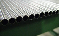
Material with rejectable defects is marked and separated from good material. The length of each tube is measured, and the material is returned to its shipping box. Tubes with rejected portions are bundled separately within the box so the rejected portions can be removed.
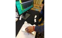
Larger material can also be scanned by hand using the contact technique. A transducer is usually mounted on a plastic wedge, and a viscous liquid couplant is applied to the material surface to allow the sound to enter the material. Contact UT is typically slower and a little less sensitive than immersion UT, but is generally more versatile, especially for very large or heavy material.
Radiographic Inspection
Radiographic inspection (often called X-ray or RT) is very similar to the medical X-rays people are familiar with. RT is used most often to find subsurface defects. X-rays are sent through a part and picked up on photographic film or a digital X-ray plate and viewed. Defects show up as a darker or lighter region in the image.
As with the other methods, the identity of the parts is established and compared to the job paperwork. Cleanliness is generally not important to the test except from a handling and housekeeping standpoint.
The parts are positioned on the film or detector and X-rays are sent through them. Note that identifying characters are used on the image to allow direct correlation between the image and the pieces. This is an important traceability step.
The image is then generated, using chemical developers for the film process and by downloading the image from the image plate for digital processes. For these parts, the dark regions show where there is a void within the part, which creates a darker region on the image.
The image is retained as a record of the test. As with the other methods, the rejected pieces are tagged and separated from the accepted pieces.
Completing the Journey
Once the testing is completed, the test results are compiled and formatted, and a test certificate containing the test results and relevant inspection information is sent to the customer. This certificate, with the test information, is the only “product” which the laboratory has made. It is nothing more or less than a promise that the testing was done properly, that the results are accurate, and that the testing was performed on specific and well-identified material.
These test results, along with all the documentation received from the customer, are maintained by the laboratory for future reference.
To summarize the traceability steps:
- Parts are matched to the job paperwork to verify the description, quantity, heat and lot numbers, etc.
- Jobs are clearly identified and always kept separated from each other during cleaning, testing, and packing.
- X-ray uses identifying characters (typically made of lead) on the image to allow direct correlation between the image and the pieces.
- Following testing, rejected material is physically marked and separated from accepted material.
- The certification provides information that clearly shows the link between the material and the test results.
Maintaining the traceability link between the test material and the test results means that the end user can be certain that the material was actually tested.


