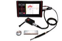
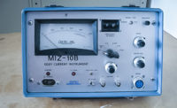
Eddy current testing uses the principle of electromagnetic induction to detect flaws in conductive materials. An excitation coil carrying current is placed in proximity to the component to be inspected. The coil generates a changing magnetic field using an alternating current, which interacts with the component generating eddy currents.
Variations in the phase and magnitude of these currents are monitored either by using a second coil, or by measuring changes to the current flowing in the excitation coil. The presence of any flaw will cause a change in the eddy current field and a corresponding change in the phase and amplitude of the measured signal. In the case of nondestructive testing (NDT), these are displayed on an eddy current flaw detector as a distinct change in signal (see figure 1).
The main advantages of eddy current inspection include:
- Provides a faster scanning speed than conventional ultrasonic testing (UT)
- Unlike UT, requires no fluid couplant
- The surfaces need minimal preparation
- Eddy current testing can be used through several millimeters of coating
- Can detect very small cracks in or near the surface of the material
- Physically complex geometries can be investigated
- The testing devices are portable
- Provide immediate feedback
- The probe does not necessarily have to be in contact with the test object
Applications
Eddy current testing can be used for a wide range of applications. It is often applied for surface crack detection and material sorting. Material sorting is used to ensure that the proper materials are in use and to verify component materials or assembly features (such as the orientation or position of a subcomponent in an assembly). Figure 2 shows the range of application types of eddy current inspection.
Flaw Detection
It’s usually carried out with pencil probes or ‘pancake’ type probes on ferrous or non-ferrous metals. Frequencies from 100 kHz to a few MHz are commonly used. Depending on surface condition it is normally possible to find cracks 0.1 mm or less in depth (as shown in figure 3).
More complex are dual or multiple frequency inspections (figure 4). These are commonly used for tubing inspection, in particular for suppression of unwanted responses due to tube support plates.
Conductivity Measurement / Material Sorting
For nonferrous materials such as aluminum and copper, eddy current electrical conductivity measurements are often used to verify material characteristics.
For raw and processed materials conductivity measurement can determine the purity of the metal.
Heat treatment of aluminum affects the metallurgical structure of the material, which in turn affects the electrical conductivity. Published charts list expected electrical conductivity values for the various heat-treat conditions of aluminum alloys.
Probe Types
Many different types of probe are used for eddy current inspection depending on the specific application.
Probe options for flaw detection include:
- Shielded probes: with their focused eddy current field, they add the ability to test very close to or materials that are dissimilar. These may be absolute or differential.
- Differential probes are sometimes used, particularly in automated applications to give enhanced sensitivity to small defects by ignoring large differences. However, care must be taken to ensure that the orientation of flaws is correct for detection and that long defects will not be ignored.
- Special low frequency probes using transmit receive connection, which may be absolute or differential
- in response.
For external tube/rod testing or sorting, outside diameter (toroidal) encircling coils allow for testing of the entire circumference of a tube. The sensor diameter is chosen based on the diameter of the tube. The tube must be centered in the test coil to ensure consistent sensitivity around the circumference.
For heat-treat and material type verification, the test material need not be centered in the test coil but positioning should be consistent for subsequent test pieces.
For internal tube inspection then an internal diameter (bobbin) probe is used.
Finally, groups of eddy current sensors may be used in tandem to form an array, which gives the advantage of higher defect resolution and removes the need to scan the probe in one axis.
Factors that affect Eddy Current Inspection
A number of factors, apart from flaws, will affect the eddy current response from a probe. In order to successfully assess flaws or any of the below factors, we must be able to minimize the effect of other factors on the results. The main factors are:
Material conductivity
The conductivity of a material has a very direct effect on the eddy current field. Conductivity is often measured by an eddy current technique and using eddy currents can help establish the different factors affecting conductivity, such as material composition, heat treatment, work hardening, etc.
Permeability
This may be described as the ease with which a material can be magnetized. For non-ferrous metals (copper, brass, aluminum, etc.), and for austenitic stainless steels the permeability is the same as that of ‘free space,’ i.e. the relative permeability (μr) is one.
For ferrous metals however the value of μr may be several hundred, and this has a very significant influence on the eddy current response, in addition it is not uncommon for the permeability to vary greatly within a metal part due to localized stresses, heating effects, etc.
For ferrous material the eddy current flow is concentrated extremely close to the surface, making sub-surface defects difficult to detect unlike non-ferrous material unless you strongly magnetize the material or use special remote field probes.
Frequency
Eddy current response is greatly affected by the test frequency chosen. Fortunately this is one property we can control. Higher frequencies reduce the depth of penetration and increase the phase difference between near and far defects making it easier to detect and differentiate smaller defects; lower frequencies increase the depth of signal penetration, enabling deeper testing to be carried out but at the cost of reduced defect sensitivity.
Geometry
In a real part there will be geometrical features such as curvature, edges and grooves and will affect the eddy current response. Test techniques must recognize this in order to maintain consistent inspection results. For example in testing an edge for cracks the probe must be scanned parallel to the edge so that small changes may be easily seen.
Proximity/Lift-Off
Moving a probe coil relative to the surface of the material has two main effects:
There will be a ‘lift-off” signal as the probe is moved.
A reduction in sensitivity as the coil to surface spacing increases.
Depth of Penetration
Eddy current inspection gives stronger signals from a flaw when that flaw is closer to the surface of the material. This signal declines with a greater depth of penetration. Higher conductivity and permeability levels in a material lead to less penetration. However, using a lower frequency can compensate for this.
Eddy Current Testing and Industry
Eddy current inspection can be used across a wide range of industries for a large number of applications. Figure 6 demonstrates the industries that this technique can be used in, the application types and what type of probe you would use to complete your eddy current inspection. This table proves that although eddy current inspection can seem complex, it is extremely versatile.


