There was a time when choosing a gaging solution for shaft-type parts was a relatively straightforward task. High-volume parts received a custom-built gage and everything else received a manual or automatic “snap-on” or ring gage of some sort. The gages used either air or contact technology and anything beyond those basic capabilities tended to reside in a metrology lab.
Things are a good bit more complicated today because you have a lot more choices in terms of hardware, software and gaging technology. Now you have to weigh factors including:
- Production volume
Higher volumes generally benefit from more sophisticated solutions, but even at very low volumes, today’s modular, re-toolable and increasingly flexible gaging systems can be economically viable across a broad range of applications.
- The machining process used.
Turned and ground parts generally require different gaging technologies because of the different surface finishes produced.
- Individual part complexity.
Access to features to be measured may require different mechanical configurations and/or multiple gaging technologies.
- Families of parts.
The number of different parts in a family and the degree to which they differ will impact the mechanical design of the gage.
- Frequency of running changes
An often overlooked consideration that can add significant cost over the life of a gaging system if it’s not planned for.
- Manual or automatic loading
Usually a volume-based decision, but also one that impacts the mechanical design of the gage.
- Gage flexibility and re-toolability
Both features are highly desirable from both a performance and a life-cycle cost-of-ownership perspective.
- Machine and gage cycle time
A critical consideration in a 100% inspection environment.
- Contact/noncontact or hybrid gaging technology
Part condition and surface finish are key factors in selecting appropriate gaging technologies. Contact technology is more effective for “rough” turned surfaces, while optical technology is best for smooth, polished surfaces.
Hybrid contact/optical systems can deliver the advantages of both contact and noncontact technologies in a single system.
- Whether the gage is measuring size/geometry or both
For highly finished parts noncontact technologies are generally best for measuring size, while contact technologies are best for measuring geometric characteristics like run out. For turned surfaces both measurements are best accomplished with contact technologies.
That’s a daunting list. Fortunately, while every application has its own set of challenges, there are some rules of thumb that can help narrow the field of competing solutions.
The first decision point is easy. If you are measuring millions of identical shafts every year and will be for many more years, a custom-engineered, robot loaded, fully-automated gage is nearly always the best, most economical solution available.
Even then, however, you will need to make choices about the measuring technology used and will probably want to build in at least a modicum of flexibility to handle minor dimensional and/or geometric changes that may be made to the part over its lifetime.
If you’re not one of the lucky few in that situation, the decision between a dedicated gage, a flexible and/or re-toolable unit, or something simpler can be a lot more challenging. The trend, however, is clearly toward flexibility and re-toolability across the board.
Relatively low-volume parts are good candidates for extremely flexible “kit” type gages. In these, probes, transducers, gages, V-blocks, centers and other components are mounted on a precision machined baseplate in virtually any configuration necessary to measure the part. They are easy to set up and easy to re-configure. On the other hand, they are usually manually loaded, have relatively long cycle times and best applied to relatively small parts.
Contemporary semi-dedicated systems for crankshafts are good examples of the state-of-the-art at the higher end of the volume spectrum. These typically utilize contact technologies and interchangeable pin followers to handle families of parts. These systems are able to measure size and geometry of cranks with different throws, pin diameters, bearing diameters and bearing axial locations. Such systems offer flexibility within a relatively narrow range with minimal changeover downtime. They are not, however, easily re-tooled or re-configured for parts outside that range.
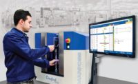
The volume middle ground is increasingly occupied by a new class of flexible, hybrid gages that combine optical and contact technologies to measure size and geometry. Since both technologies are available, these systems can be applied to parts with turned and ground surface features, as well as to geometries such as re-entrant cam lobe profiles.
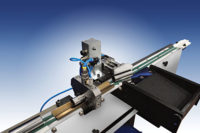
A typical example of this new class of gages utilizes Shadowcast technology for the optical measurements, and a precision gaging probe for the contact measurements. The light sources and receivers and the mechanical probe are movable along the length of the part to measure multiple features. Motions are under program control and positions are tracked with precision glass scales.
Shadowcast technology uses a calibrated light source on one side of the part and an optical sensor on the other. The sensor counts the pixels in the shadow cast by the part to determine the diameter with an accuracy of ± 0.1 micron.
The mechanical scanning probe can measure features like key slot widths or other non-visible features, like run out, with an accuracy of ± 0.5 micron. The accuracy difference is explained by the fact that the contact probe uses position data from both a glass scale and a rotary encoder to determine run out and any encoding errors are cumulative.
This particular system can be manually or robotically loaded, and has a cycle time of roughly 60 seconds measuring a typical crank or camshaft. Today, this kind of system is most often used to audit families of parts or batch runs of multiple part types,
Note, however, that its 60 second cycle time is a 20% improvement over the first generation of these machines. As the technology advances, such hybrid systems will almost certainly become fast enough for a broad range of 100% inspection applications. They also will be able to measure more complex features like gear teeth, threads and splines, which are typically found on automotive shaft-type parts.
The next breakthrough in shaft measurement is likely to be a laser-based application, but that is still in the future. For now, and the next few years, flexible, hybrid systems combining optical and contact mechanical technologies will be the optimal gaging solution for the vast majority of production applications.
For a while, anyway, choosing the right solution actually may be a relatively straightforward task for most of us once again.


