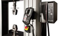
They’re as common as dandelions in the spring, and as universal as a Swiss army knife. Sometimes they gather dust, condemned to a dark corner, other times they’re polished to a mirror finish from intensive everyday use. We’re talking, of course, about universal testing machines (UTMs).
Why universal? Historically, force testing machines were called tensile testers, because they were only capable of pull forces. Adapting them to compression use required the use of a mechanical cage, converting tensile forces to compression forces, resulting in additional measurement errors. Later pioneers developed the UTM, with the added ability to pull and push without the use of adapters.
Today, the term UTM is used interchangeably with “materials tester” to reflect their primary use. A UTM tests a wide range of materials and assemblies, providing quality control and engineering staff with valuable data. The test results are primarily used to characterize materials, but can also be used for pass/fail testing of finished items and assemblies.
Configuring a UTM
A UTM consists of the following major components:
- Load Cell
- Test Frame
- Encoder / Linear Scale
- Data Collection Software
- Grips and Fixtures
1. Load Cell
A strain gage-based load cell is at the heart of most measurement systems within a UTM. Strain gages applied to a deformable structure stretch and compress as the structure is loaded. As the gages deform, their electrical resistance changes, upsetting the balance within a balanced circuit. This imbalance is measured, amplified, and processed by data acquisition hardware. The signals are converted into digital form, usable by indicators and PCs. The data is presented in selectable units of measurement, such as lbF, kgF, and kN.
In certain basic UTMs, a load cell and its associated electronics may be substituted by a force gage. A force gage integrates a load cell and indicator within one housing. A force gage is capable of performing certain functions in a more efficient manner than a PC, such as peak force capture, high speed data capture, and other real-time functions where speed and timing is critical.
2. Test Frame
UTMs range in force capacity, reflecting a broad range of applications—from peeling open a bag of potato chips to crushing a concrete bridge support. They can be single-columned, generally for lower forces, or twin-columned for higher forces. Most UTMs are driven by one or two lead screws, while some machines utilize hydraulics, especially for cyclic testing applications.
Force accuracy is most affected by the range and accuracy of the load cell. UTMs may be fitted with a wide range of load cell force capacities. For example, a 10 kN capacity machine may be used with a 500 N load cell for a wire crimp pull test, and then switched to a 10 kN load cell for tensile testing on a metal strip.
3. Encoder or Linear Scale
Many applications require the measurement of sample deflection in addition to force, such as spring and tensile testing. In those cases, an integrated encoder or linear scale can measure travel distance as the screw moves the crosshead up and down. Where small deflections are expected, such as the tensile testing of metals, an extensometer provides significantly better resolution. Extensometers eliminate the errors introduced by frame and load cell bending. An extensometer physically clamps to two points on the sample and measures the stretch or compression between them. More recent technologies include noncontact video and laser methods.
4. Data Collection Software
In some cases, raw force and distance data is sufficient, however, in many applications the power of a UTM shines via data collection software, which calculates results in a presentable, useful fashion. For example, an elongation test of an elastomeric strip can be represented by a plot of force vs. distance, or stress vs. strain. As the sample reaches and exceeds its yield strength, the arc of the curve changes until it reaches its ultimate strength, and finally drops to its breaking point. A wealth of information can be derived by analyzing the curve, including spring rate, Young’s Modulus, and many other values. More advanced software packages can automatically calculate these values, and overlay previous test results for comparison purposes.
5. Grips & Fixtures
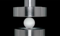
To address the virtually unlimited number of applications, many standard grips have been developed over the years. Common types include parallel jaw grips for fabrics and films, wedge grips for plastics and metals, compression plates for springs and foams, and others. Most standard grips utilize eye end adapters to mount to load cells, force gages, and machine bases. This method utilizes a pin and jam nuts to prevent the grip from loosening, and provides a quick way of switching grips for different tests.
UTMs vs. Force Testers
Although a vast gray area straddles the border between force testing and materials testing, a UTM can satisfy both applications. Its configuration, in particular its distance measuring technology and data processing capabilities, determines whether it’s a force tester or a materials tester. The answers to the following questions can help determine the sophistication required to perform a test:
- Is force vs. deflection data required, or just force?
- Is just a peak force required, or does the application require a curve of force vs. time or force vs. deflection?
- How much deflection measurement is required?
- Are any specific calculations required, such as spring rate, percentage elongation, Young’s Modulus, etc.? Or, is the requirement more simple—for example, maximum force, distance at break, or force at given distance?
Is it overkill?
Modern force testers are capable of performing many functions historically reserved for UTMs. However, an important consideration to remember is that a UTM can perform force testing, but a force tester cannot perform materials testing.
Force testers have a lower cost of ownership when compared with materials testers of equal load capacity. They are ideal for dedicated, well-defined applications not requiring sophisticated data analysis or an extensometer. However, force testers’ simplicity can limit their usefulness in an environment with a diverse and ever-changing set of applications. In such situations, a cost-benefit analysis may tip the balance in favor of a UTM, even if its full capabilities are not utilized every day.
Caring for a UTM
Aside from standard preventative maintenance procedures such as lubrication of lead screws and bearings, calibration is the most important service for a UTM, in order to ensure measurement accuracy. With some UTMs calibration can only be done on-site, at the machine. With other UTMs, the force gage or load cell with associated electronics can be removed and sent to a calibration laboratory. Either way, a regular calibration schedule is important to ensure that ongoing testing is accurate.
With the proper maintenance and periodic calibration, a UTM should be a loyal workhorse for many years, hopefully developing a fine polish over time instead of a fine layer of dust.


