
Additive manufacturing (AM) is one of the hottest and most revolutionary processes to come along in many years. The thought of popping a design into a machine and having a functional part come out the other side was science fiction a generation ago. We are nowhere near the Star Trek replicators, but we are closing that gap.
Plastics, infused plastics, ceramics, inks, precious metals, and exotic alloys are manufactured daily across a variety of industries and for a plethora of applications and uses. The range of applications is amazing. Everything from toys to human organs are being printed. Here I will focus on the aviation and power generation side of AM where many are hard at work designing and creating innovative solutions.
In these areas, components being manufactured using AM have become more complex and are being accepted and used in increasingly more critical applications. These applications are just the beginning of where industry wants to go with AM. In the near future, AM powders and alloys will reach new levels of component and design capabilities.
Perhaps though, it is time to take into consideration the actual inspect-ability of the unique and highly optimized shapes that AM is producing. Inspect-ability and metallurgical validation must be an integral part of the AM design and process parameters. There is a real need to discuss the current state of inspection, where it is today, and where it may need to go in the future.
Before I dive in to my main focus of AM inspection, let me first give you a little information on additive manufacturing of metallic complex components.

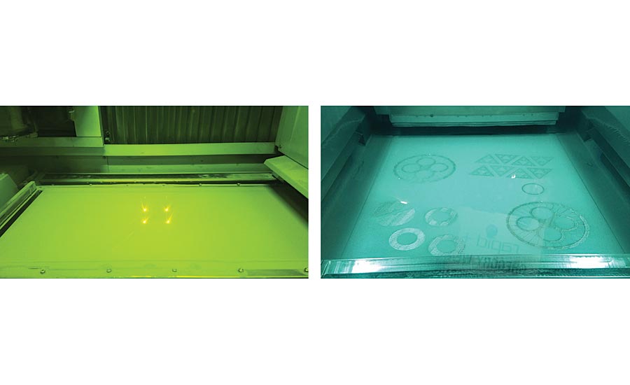
Nonmetallic additive manufacturing images. Source: Weaver
First off, AM is not just a single technology, but instead is a group of technologies. AM (commonly known as 3D printing) technologies are broken into two main groups: Powder Bed Fusion (PBF) and Direct Energy Deposition (DED).
Each of the two groups have multiple methods within them.
PBF
- Direct Metal Laser Sintering (DMLS)
- Selective Laser Sintering (SLS)
- Selective Laser Melting (SLM)
- Electron Beam Melting
DED
- Gas Tungsten Arc (GTA)
- Plasma Arc (PA)
- Gas Metal Arc (GMA)
- Plasma Transferred Arc (PTA)
- Laser Beam (LB)
- Electron Beam Freeform (EBF)
Without getting too deep into any of these methods in particular, let me explain the difference between PBF and DED.
In PBF, a uniform powder layer is fed onto a deposition plane where an electron beam or laser is directed. The energy of the beam or laser melts and fuses at all the designated locations in the plane. When that plane is completed, the system indexes to the next plane and the process repeats. This continues until the components are fully built. In PBF, the deposition plane is fixed in the x and y axis and only moves in the z axis once the current build plane is completely fused.
Metallic Powder Bed Fusion additive manufacturing images. Source: Weaver
In DED, a powder or wire material is supplied to a melt pool in synchronization with an energy source which is again an electron beam or laser. Just as with PBF, the energy from the beam or laser will melt and fuse the material, but unlike PBF, the deposition spot is not fixed in X and Y. This means that either the surface being built and/or the energy source will be moving in relationship to the build design. DED is also different in that the building of the part layers can be in nearly any direction. This is a drastic difference between the two different AM approaches.
So, both PBF and DED are methods of melting and fusing materials into designed shapes and both can create complex shapes. The difference is the how the material is introduced and how each layer is indexed.
Hopefully this has given you an overview of metallic AM and of the two main AM groups.
Now that we know how AM works, you can probably imagine many advantages over casting and forging methods. A few of these advantages are building parts without molds, in many directions, with very complex shapes, building several parts of different designs at the same time, and even multipart consolidations. This manufacturing technique is nearly boundless, so we need to be sure we also consider the inspect-ability of the produced components.
While current AM inspections are in many ways no different than those for castings and forgings, where parts are subjected to visual, dimensional, external and internal testing, and also surface roughness tests, they can also be quite different, as many of the components are consolidated and redesigned. The consolidated parts (where multiple parts are reduced into one part) are of particular interest as they incorporate several part geometries into a single new design. As AM is more broadly accepted, the inspection community needs to keep up and ensure that the integrity of the product is maintained at the highest level of quality possible.
I have already mentioned that AM products are subjected to many of the same inspections as castings and forgings, but now let’s take a look at those inspections in detail.
The typical external surface inspections are: fluorescent liquid penetrant (PT), visual (VT, typically enhanced up to 10x), surface roughness, and a dimensional check. Dimensional can be accomplished using gages, coordinate measurement machines (CMM), and white/red/blue light scanners. The typical internal inspections are radiography (RT), electromagnetic (ET), ultrasonic (UT) and in rarer cases even computed tomography (CT).
Each of the inspections serve the same purpose regardless of the method of manufacturing, but the differences in the new manufacturing methods is stark. Castings and forgings are full body methods of manufacturing, meaning that the entire component is formed at one time. AM products are built in layers, typically from .001” to .003” thick depending on the system and the material. This difference is why there must also be a renewed and most likely different focus on inspection.
Traditional nondestructive inspections are performed much the same for the AM parts, but there are some new limitations introduced by the AM methods. The limitations are driven mainly by surface roughness and thin layer build. Some AM parts have excessive surface roughness, at least in some areas, that make PT, VT, ET, and UT nearly impossible. The roughness makes interpretation of the visual methods very difficult and subjective. It also makes the use of contact probes unmanageable.
Knowing the limitations of these particular inspection methods, most AM manufacturers have turned to radiographic internal inspections to validate their parts. RT, especially digital RT (DR), and CT are currently the go-to inspections for many AM manufacturers. The inspections are used both to detect gross defects and to confirm internal geometry. These are decent inspections for these purposes, with CT being much more capable for geometry validation and DR being better at gross defect detection. Unfortunately, neither is as sensitive as required to confirm if defects are present or not at the single layer level.
The building/growing/printing of an AM part in layers can introduce discontinuities that do not form in castings and forgings. Each individual layer is prone to having possible defects and with each layer being so thin, inspection sensitivity or resolution can be critical. DR and CT sensitivity and techniques may be suitable for the larger defects produced by AM, but with the build layers being about 1/3 as thick as the best X-ray resolution levels, the X-ray is capturing three layers of the component at a time. Layer-level defects, a realistic problem with AM processes, are nearly invisible to CT. On top of the resolution issue, geometrical and density challenges limit both of these inspection methods and can make the DR and CT interpretation very subjective and unreliable. Thicker walls, internal cavities, radii, and just plain accessibility are all limiting factors with conventional NDT methods.
All the external inspections are hampered by surface roughness and the internal radiographic inspections are very limited due to poor resolution, so the assessment of where we are today is basically that we are trading the benefits of additive manufacturing for the significant reduction in inspection confidence from the traditional nondestructive inspections. Most companies are validating each build with a destructively tested metallurgical sample. These samples are built on the same build plate as the products, under the same conditions, so the thought is that if the sample tests within metallurgical limits, then the products built under the same conditions should be acceptable as well. So, are all the parts representative of the tensile sample? Is one part next to another the same?
We now know what most of the industry is facing with the current and standard technologies. What is needed now is an inspection method that is capable of measuring and assessing each AM-produced component quantitatively, a method that is driven by the part’s structural integrity. There are not many choices of inspection that can provide this, but one worth discussing is Process Compensated Resonance Testing or PCRT.
PCRT is a method that is showing great promise in AM research. PCRT is a whole-body inspection method that uses part resonances, also called natural frequencies, which are sensitive to the material/integrity/dimensional condition of the whole part. PCRT identifies parts that are structurally different in ways that will adversely affect the performance or material properties of the part. PCRT does not identify cosmetic indications. It is a whole-body, structural inspection using statistical processing and pattern recognition tools to segregate parts that are non-conforming. It is both an internal and external inspection all in one.
PCRT data can be used to monitor each part after build to ensure compliance with a given acceptance range or tolerance, or it can be taught to detect printed samples with specific defect types or even carefully modeled defects. PCRT analyses learn by example. Acceptable part variation, and unacceptable defective conditions like porosity and lack of fusion, can be taught with physical samples, or can be modeled for predictive responses and then those modeled responses can be programmed into an algorithm for detectability. This allows for very quick detection of known structural issues.
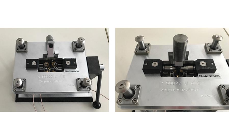
Process Compensated Resonance Testing fixture with additive manufacturing dogbone. Source: Vibrant
PCRT cannot generally be used yet to locate, size or characterize defects, although PCRT measures will report which samples are most different from the nominal reference set. PCRT can be used to segregate parts within the same build plate that may have single layer defects that are currently undetectable using DR and CT. In sample population AM studies, PCRT has been used to detect unacceptable levels of porosity, cracking, lack of fusion, and even sub-optimal heat treatment in AM components. This is also a relatively fast process. Measurements take from 30 seconds to three minutes per part, so it can be used as a 100% inspection method. It requires no chemicals and produces no waste. PCRT should be performed on individual components, removed from the build plate.
PCRT inspections are already in use in commercial aerospace applications on complex geometries, improving component reliability while reducing inspection and part replacement costs, and may represent the future of AM component inspection. The current suite of inspections is not providing the individual part validation that is needed and the industry is currently relying on an assumed representative tensile sample to confirm material conformance of batches of parts. PCRT meets both of these needs, providing a production-ready, 100% inspection option that quantifies inspection results, supporting process monitoring, quality assurance, and continuous improvement. Q


