
When do you need to be concerned about the effects of temperature in your inspection process, how significant is it and how do you deal with it? These can be tricky questions to answer. However, understanding the effects of temperature on your measurement system and being aware of the three common methods for managing temperature effects, can go a long way toward getting a handle on these questions. But first, some important concepts…
The Measurement System
The three core elements of a measurement system that require attention when assessing temperature effects are the measuring instrument, reference standard, and workpiece. Each of these components are affected by temperature. Assessing the degree of their contribution to error can be complex and will vary dependent on size, material, geometry, environment, electronics and technique.
The Measurement Environment
When it comes to measurement, limiting the temperature change of your environment is as paramount as cleanliness. Constant high temperature or constant low temperature can be dealt with (See Compensate below), but a changing temperature is unmanageable. To ensure the best accuracy during your inspection process, temperature changes in your environment need to be at a minimum. A constant temperature environment promotes thermal equilibrium.
Thermal Equilibrium
A material has reached thermal equilibrium when there is no more temperature change in the material. This can be achieved by soaking in a constant temperature environment or insulating the material from its environment. In many cases if the temperature of your part is only moderately above or below the ambient, the surrounding air is sufficient to assume thermal equilibrium since still air is a relatively poor conductor of heat. Accurate measurement cannot be achieved unless an acceptable level of thermal equilibrium is reached.
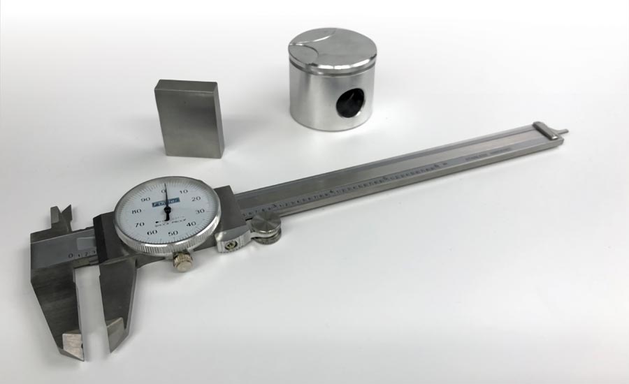
Components of a Measurement System - caliper (measuring instrument), reference standard (gage block) and workpiece (piston).
Temperature Gradient
A temperature gradient is the non-uniformity of temperature within the body of a part. The temperature gradient is a function of the material’s thermal conductivity—and a gradient will be present until total thermal equilibrium is reached. This can be important because with temperature gradient, the surface temperature will not reflect the temperature at the core of the part—resulting in errors in your assessment.
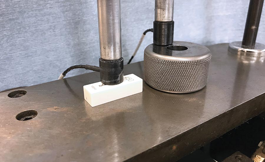
Temperature sensing of the reference standard and the workpiece.
Temperature Measurement
Depending on how you choose to manage temperature effects (see managing temperature effects below), you may be required to measure the temperature of the environment, the temperature of the measurement system components, or all of the above.
Workpiece and reference standards are measured by direct contact with the sensor. Low mass, high sensitivity sensors such as thermocouples and RTDs are best suited for quickly responding to the temperature of the part. Measurement of the environment temperature is easily handled by chart recorders or data loggers with built in sensors. Instruments, tooling and fixturing are difficult to measure with their various surfaces, materials and electronics—the easiest approach here may be to allow for thermal stabilization and assume that they are at the same temperature as the ambient.
Standardized Temperature
It is well understood that when materials are exposed to changes in temperature they will expand and contract in size to varying degrees. For this reason, to compare a feature length, one must express the length at an agreed upon reference temperature; otherwise known as standardizing.
The universally agreed standard reference temperature for linear measurements is 20°C, which corresponds to exactly 68°F.
“To compare a feature length, one must express the length at an agreed upon reference temperature; otherwise known as standardizing.”
Coefficient of Thermal Expansion
How much a material changes in size with every degree change in temperature is expressed by the “Coefficient of Thermal Expansion,” CTE. The CTE value is specific to each material type and is accepted as a constant value at temperatures around the standard temperature. Table 1 lists the values for some common materials. Note that the CTE values are dimensionless in linear units, but it is useful to think in terms of in/in-ºF or mm/mm-ºC.
Change in Length
With the type of material and the CTE known, and the temperature of the material measured, the change in length that a part experiences as it deviates in temperature away from some reference temperature, can be calculated with the following equation:
∆L=L x CTE x ∆T EQ.I
Where L is the length of the material at the reference temperature, DL is the change in length, CTE is the coefficient of thermal expansion, and DT is the workpiece temperature minus the reference temperature; equal to (Twp – 68ºF or Twp – 20 ºC) when the reference temperature is the standard temperature.
Note that holes (diameters) in objects of uniform temperature experience exactly the same expansion as a bar of the same length. Just replace diameter D with length L in the equation.
Now let’s move forward and take a look at how to best deal with temperature effects in the inspection process.
Methods for Managing Dimensional Change Due to Temperature
The effects of temperature are managed with three broad approaches: control, compensate, and match. Each approach is an attempt to express the length at the standard temperature. Note that in this discussion, error is defined as the feature length at-temperature relative to the feature length at-standard-temperature. The three approaches can be used in combination to achieve the best results.
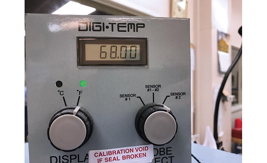
Temperature sensor digital readout - sensing workpiece and reference standard at 68oF.
Control
A dimensional measurement will be free of temperature induced error if all components are thermally stabilized in a 68º F environment. This is the intent of the control approach. It simply means that before a measurement is taken, bring the workpiece, reference standard and measuring instrument to the internationally recognized standard temperature. It is the most direct approach—and in its most basic form it means conducting your measurement process in an air conditioned room set at 68 ºF. Equation I can be used to determine the temperature induced dimensional error that may be experience due to the high and low temperature control zone of your air conditioning system.
| Material | CTE (per oF) | CTE (per oC) |
| Aluminum, pure | 12.8 x 10⁻⁶ | 23.0 x 10⁻⁶ |
| Copper, pure | 9.2 x 10⁻⁶ | 16.6 x 10⁻⁶ |
| Steel alloys, low carbon | 6.5 x 10⁻⁶ | 11.5 x 10⁻⁶ |
| Stainless steel, 300 series (18Ni, 8%Cr) | 9.4 x 10⁻⁶ | 17.0 x 10⁻⁶ |
| Chromium carbide | 4.7 x 10⁻⁶ | 8.5 x 10⁻⁶ |
| Tungsten carbide, grade C-2 | 2.8 x 10⁻⁶ | 5.0 x 10⁻⁶ |
| Zirconium dioxide | 5.6 x 10⁻⁶ | 10 x 10-6 |
| Nylon, Kevlar reinforced | 16 x 10-6 | 29 x 10-6 |
| Nylon, general purpose | 40 x 10-6 | 72 x 10-6 |
| Teflon (process dependent) | 35 to 65 x 10-6 | 63 to117 x 10-6 |
| Acrylic plastics (process dependent) | 40 to 130 x 10-6 | 72 to 234 x 10-6 |
Table 1 – Coefficients of Thermal Expansion
Compensate
Compensate means making a mathematical correction to the measured size when the temperature of the part or the environment is not at the standard temperature. As with all the methods described here, the compensate method requires a good level of thermal stability and can be applied to scale or comparator type instruments. Here’s how in four simple steps,
- Compute the at-temperature length of the reference standard using EQ. I
- Zero or scale (master) the instrument using the at-temperature size of the reference standard(s)
- Gage the workpiece – displaying the at-temperature size of the workpiece
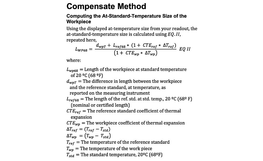
- Correct the reading by calculating the size of the workpiece to at-standard-temperature using EQ.II below,
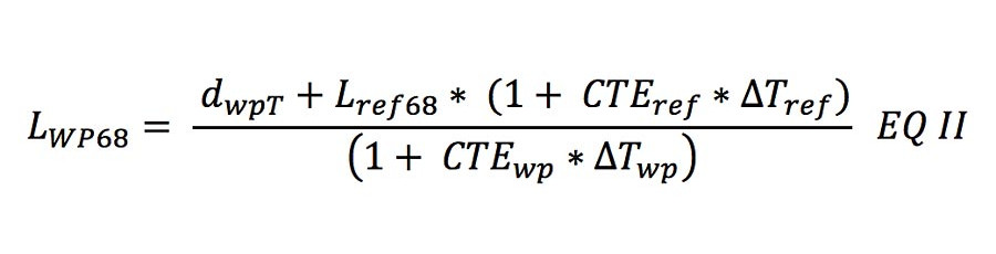
In this equation dwpT is the difference in length between the workpiece and the reference standard at temperature as reported by the measuring instrument. For a more thorough explanation of this equation, see the sidebar.
The implications and benefits of the compensate method are:
- The instrument can be mastered once, or per your normal schedule, and all subsequent inspections of workpieces can be corrected for size using the measured temperature of each workpiece.
- If the temperature of subsequent workpieces change, re-mastering is not required – only measurement of the workpiece temperature and calculation (EQ II) of the at-standard-temperature size correction is necessary.
- If re-mastering the instrument is necessary, the temperature of the reference standard must be measured again and used to compute (EQ I) the at-temperature size for the mastering step.
- The effect of temperature on the instrument is not considered here. A complete temperature compensation program will include the instrument effects.
- Uncertainties are not eliminated by temperature compensation.
Match
This method involves using a reference standard that is the same material as the workpiece, and ensuring that the workpiece and reference standard are thermally stabilized in the same environment (i.e. at the same temperature). Doing so effectively eliminates any temperature effect.
The reasoning behind this method is that if the materials are the same, the coefficients of expansion will be the same or very close to the same. This ensures that the two components will have the same degree of expansion and contraction with temperature. Furthermore, by ensuring that the two components are at the same temperature, you now have a master and workpiece that lengthen or shorten exactly the same at any temperature.
Mastering is done with the nominal value of the reference standard, and you do not have to control the temperature at 68º F, nor make any post measurement corrections. Measurements taken under these conditions will show little to no effect from temperature, as long as your instrument is thermally stabilized also.
There are some practical limitations inherent to this method. Selecting a material similar to the workpiece, such as plastics and aluminum alloys, may result in a material that has too high expansion and contraction properties, is too soft or has inadequate wear properties. This often makes these materials inadequate for dimensional gages or setting masters. Steel gage blocks, while most nearly matching the CTE of steel workpieces, do not wear nearly as well as tungsten carbide, chrome carbide or ceramic, which are much harder and provide better overall accuracy. Waiting for thermal stabilization can also be prohibitive in a fast paced production environment.
Despite these drawbacks, this technique was the means of ensuring accurate measurements in manufacturing environments for many decades before wide use of modern heating, ventilation and air conditioning, and before readily available temperature sensors. Q


