
GD&T is an acronym that stands for Geometric Dimensioning and Tolerancing. It is a symbolic language used by designers to communicate manufacturing constraints and tolerances clearly. This information is conveyed in the form of annotations included in the design of the part.

To start, the designer encodes the information into the model, using GD&T’s specific grammar and syntax rules. This eliminates the lengthy notes in a drawing that used to be used to describe the form. With GD&T we have a broad range of tolerances, giving the designer a certain flexibility to communicate dimensional constraints based on the requirements of the part.
When it is time to validate the part, the Inspector then decodes the information, which describes tolerances for the fit, form, and function of the part.
The goal of implementing Geometric Dimensioning and Tolerancing is to avoid confusion, scraps, and rework, all of which lead to a loss of profit.
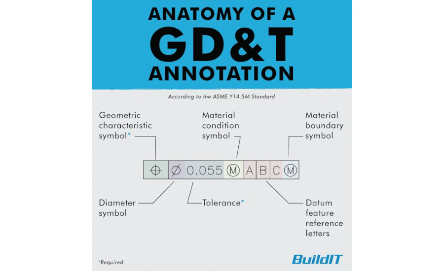
Diagram of a GD&T annotation using the ASME Y14.5 standard. (Click on the image to enlarge.) Image courtesy of FARO
Types of GD&T Tolerances
How does GD&T help manufacturers avoid scraps and rework?
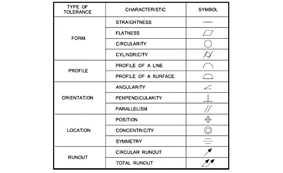
Chart showing the different types, characteristics, and symbols of GD&T tolerances using the ASME Y14.5 standard. (Click on the image to enlarge.) Image courtesy of FARO
One aspect of an explicit language is that the tolerances are better defined. They have a precise and functional definition and because of this, you can have looser tolerances. This means more parts will be able to pass inspection, which in turn enables a lower production cost.
The precise and functional definitions tell the Inspector exactly how to align the part, what to measure, and how to calculate that measurement correctly. When used properly by well-trained personnel, Geometric Dimensioning and Tolerancing allows efficient communication between the design and metrology departments, helping to eliminate false positives and false negatives.
GD&T in practice
If you have ever performed a GD&T inspection, you know that using it does come with some challenges. One common issue is that Geometric Dimensioning and Tolerancing can be easy to misinterpret. While the annotations and definitions make sense, it takes training on the part of both designer and inspector to properly apply and interpret them.
Another issue with implementing GD&T effectively is the need for the tolerances to be “semantic”; they must conform to a logic set by the standard (ASME or ISO), are embedded in the model and refer directly to the geometries. Design software will sometimes allow for semantic GD&T, but will never enforce it. Due to this, designers can use annotations as they see fit, whether the tolerances follow the ASME/ISO logic or not. If they do not fully understand the implications, non-semantic GD&T can cause problems for the Inspector. In these cases, quality inspectors are tasked with interpreting the ambiguous tolerance to match the designer’s intention and then determining the feasibility of the inspection. A lot of the time wasted here can be saved by properly defining a tolerance from the get-go.
Conclusion
Geometric Dimensioning and Tolerancing is a way of encoding tolerances in a clear and concise manner. Done properly, it can improve the quality of your manufacturing process. However, if the personnel is untrained in the interpretation of GD&T and the semantic encoding of the tolerances, then it is less effective in avoiding confusion, scraps, and rework, all of which lead to a loss of profit.
Get in touch with a FARO representative to learn more here: www.faro.com