
Introduction
Composite tolerances in GD&T define multiple levels of positional control for patterns of features. Given their multi-layered complexity, they may look very challenging at first sight. The goal of this article is to present different variations of composite tolerances and discuss their differences. The difference between composite positional tolerances and single-segmented positional tolerances will also be discussed.
Composite tolerances are used when we have relatively looser location requirements but tighter orientation tolerances. The full definition of composite tolerances can be found in section 10.5 of the ASME Y14.5-2018 standard[1].

A simple example would be a set of holes (pattern) used to affix a name plate. The relative position of the holes is important (tighter tolerance), in order to match the same hole on the plate itself, but the absolute position of the entire pattern on the part may be less critical (looser tolerances) as long as the orientation is good.
In this blog post, we shall present the following variations of positional tolerances:
- Composite tolerance with only primary datum in the lower segment
- Composite tolerance with primary and secondary datums in lower segment
- Two Single-Segmented Position Tolerancing
Terminology:
In the ASME Y14.5 standard, a feature control frame is a rectangle divided into compartments containing the geometric characteristic symbol, followed by the tolerance value and datum references. Composite position tolerances and two single-segment position tolerances follow the same logic with one major difference:
- In composite tolerances, the geometric characteristic symbol contains a single entry (Figure 1)
- In two single-segment feature control frames, there are two separate geometric characteristic symbols (Figure 2)
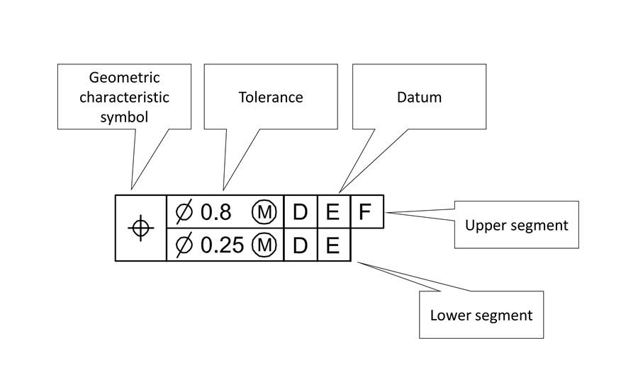
Figure 1. Composite feature control frame. (Click on the image to enlarge.) Image courtesy of FARO
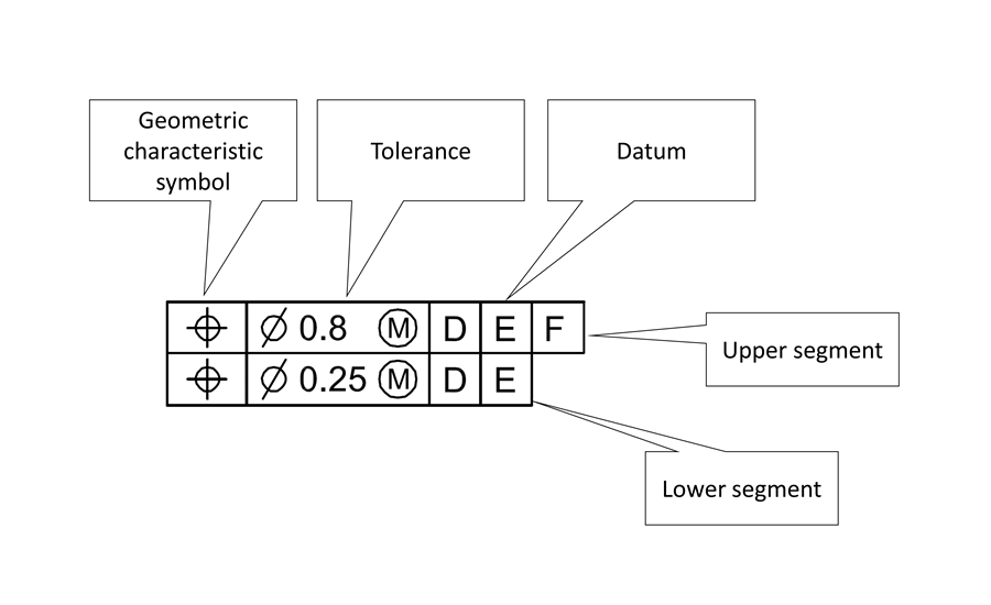
Figure 2. Two single-segment feature control frame. (Click on the image to enlarge.) Image courtesy of FARO
Composite tolerance with only primary datum in the lower segment
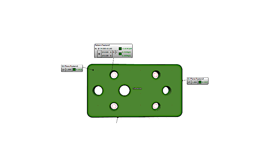
Figure 3. Hole pattern with only primary datum repeated in the lower segment of composite position tolerance (created in BuildIT Metrology Software). (Click on the image to enlarge.) Image courtesy of FARO
In Figure 3, we observe a composite tolerance created using BuildIT Metrology Software. The algorithms implemented in the software evaluate the measured features according to specifications of ASME Y14.5, explained in this post.
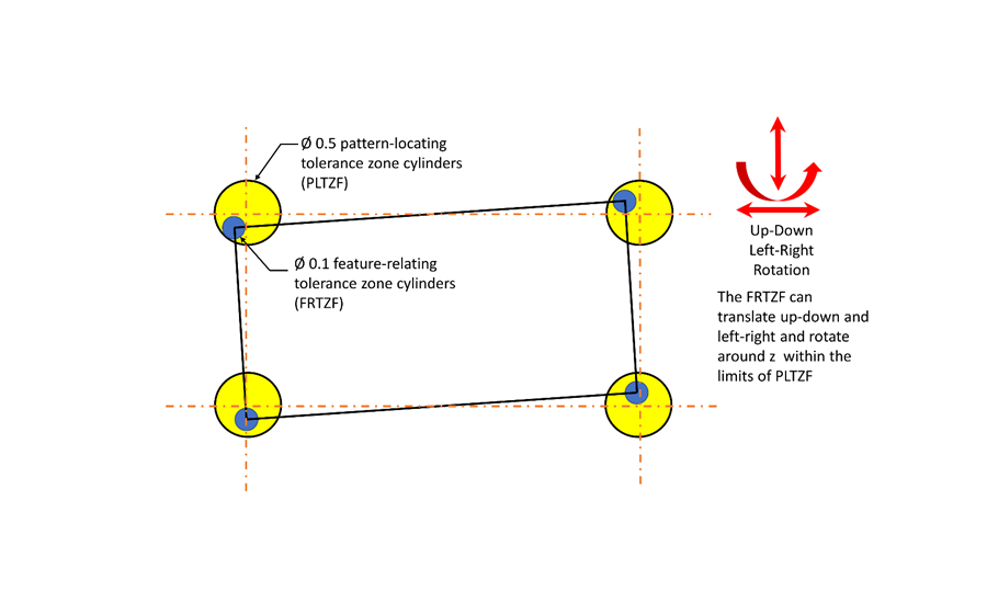
Figure 4. Hole pattern located by composite tolerancing (Primary datum only in lower segment). This figure represents one of the possible displacements of the pattern. Note that the yellow and blue circles represent the tolerance zones with 0.5 mm and 0.1 mm diameters, respectively. (Click on the image to enlarge.) Image courtesy of FARO
Figure 4 shows the tolerance zones and their functions for composite tolerances with only primary datum in the lower segment:
Yellow Tolerance Zones: Pattern locating tolerance zone framework (PLTZF).
Blue Tolerance Zones: Feature relating tolerance zone framework (FRTZF).
The PLTZF constrains the location and orientation relative to datum ABC.
The FRTZF:
- Constrains the location and orientation of individual hole features within the pattern
- Constrains the orientation only relative to datum A
The axis of the holes must reside within the tolerance cylinders of both the PLTZF and FRTZF.
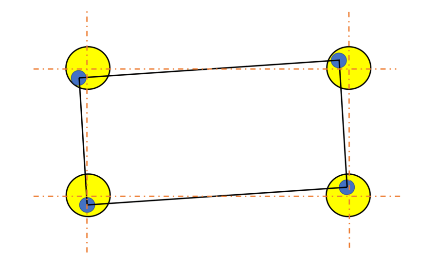
Figure 5. Animation showing hole pattern located by composite tolerancing (Primary datum only in the lower segment). Any of the displacements in this animation represents a possible configuration for composite tolerancing with only primary datum in the lower segment. Note that the yellow and blue circles represent the tolerance zones with 0.5 mm and 0.1 mm diameters, respectively. (Click on the image to enlarge.) Image courtesy of FARO
In the animation in Figure 5, the yellow tolerance zone pattern designates the PLTZF and the blue tolerance zone pattern designates the FRTZF.
Again, the important difference between the upper and lower segment is that in the lower segment, the tolerance zones are only constrained in orientation with respect to datum A. The lower segment does not locate. Thus, the blue tolerance zones (the FRTZF) are free to translate and free to rotate with respect to datum B or C and stay inside the larger tolerance zones.
Note that in certain positions, portions of the smaller blue tolerance zones can fall beyond the limits of the larger yellow tolerance zones. However, these portions of the smaller tolerance zones are not usable because the axes of the features must not violate the limits of larger tolerance zones (ASME Y14.5-2018, 10.5.1.1).
Composite tolerance with primary and secondary datums in lower segment:
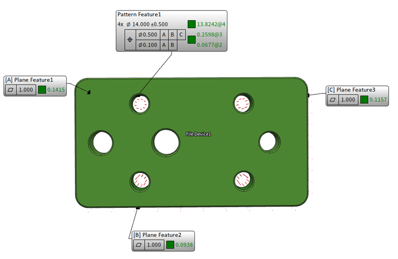
Figure 6. Hole pattern with primary and secondary datums repeated in the lower segment of composite position tolerance (created in BuildIT Metrology Software). (Click on the image to enlarge.) Image courtesy of FARO
In composite tolerances with primary and secondary datums repeated in lower segment, one more degree of freedom is constrained. In Figure 6, we can see an example of a composite tolerance with primary and secondary datums in the lower segment created using BuildIT Metrology Software.
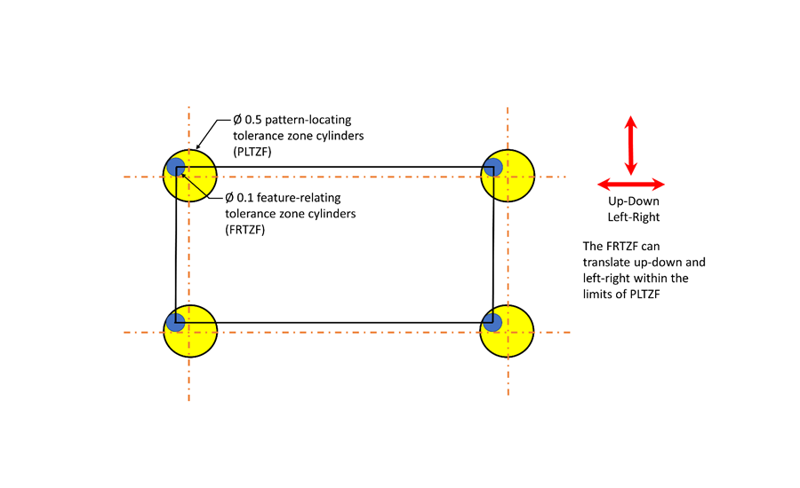
Figure 7. Hole pattern located by composite tolerancing (primary and secondary datums in lower segment). This figure represents one of the possible displacements of the pattern. Note that the yellow and blue circles represent the tolerance zones with 0.5 mm and 0.1 mm diameters, respectively. (Click on the image to enlarge.) Image courtesy of FARO
Figure 7 shows the tolerance zones and their functions for composite tolerances with primary and secondary datums in the lower segment:
Yellow Tolerance Zones: Pattern Locating Tolerance Zone Framework (PLTZF).
The PLTZF constrains the location and orientation relative to datum ABC.
Blue Tolerance Zones: Feature Relating Tolerance Zone Framework (FRTZF).
The FRTZF:
- Constrains the location and orientation of individual hole features within the pattern
- Constrains the orientation only relative to datum A and datum B.
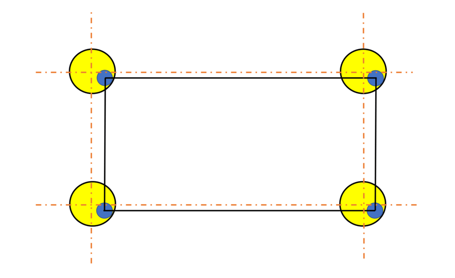
Figure 8. Animation showing hole pattern located by composite tolerancing with primary and secondary datums in the lower segment. Any of the displacements in this animation represent a possible configuration for the composite tolerancing with primary and secondary datums in the lower segment. (Click on the image to enlarge.) Image courtesy of FARO
The important difference between the upper and lower segment is that in the lower segment the tolerance zones are only constrained in orientation with respect to datums A and datum B. The lower segment does not locate with respect to datums A and B. Thus, the FRTZF can move up and down and right and left (Figure 8).
Two single-segmented position tolerancing:
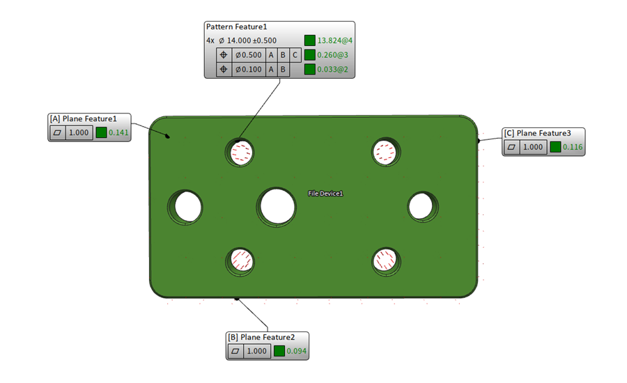
Figure 9. Two single-segmented position tolerancing (created using BuildIT Metrology software). (Click on the image to enlarge.) Image courtesy of FARO
Two single segmented position tolerances are not composite tolerances. An example of this can be seen on Figure 9. Both segments control the location and the orientation defined relative to their datum reference frames.
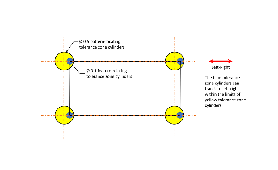
Figure 10. Hole pattern located by two single-segmented position tolerancing. (Click on the image to enlarge.) Image courtesy of FARO
Figure 10 shows the tolerance zones and their functions for two single-segmented position tolerancing:
Yellow Tolerance Zones: Represent the upper segment.
The upper segment constrains the location and orientation relative to datum ABC.
Blue Tolerance Zones: Represent the lower segment.
The lower segment constrains the location and orientation relative to datum A and datum B.
As shown in Figure 10, the blue tolerance zones are now also located by datum B (as opposed to composite tolerances which only constrained orientation). They are only free to translate left and right, as datum C allows.
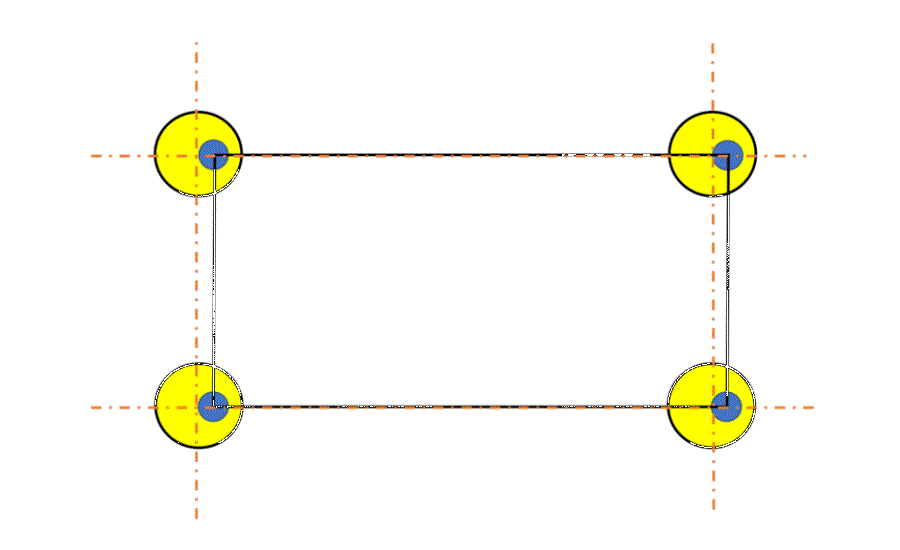
Figure 11. Animation showing hole pattern located by two single-segmented position tolerancing. (Click on the image to enlarge.) Image courtesy of FARO
As shown in the animation on Figure 11, now the lower segment also constrains the location, in addition to the orientation. Thus, the blue zones are also constrained in moving up and down (the location constraint imposed by datum B). They can only move right and left, since the datum C is not constrained in location.
Conclusion
Composite position tolerancing is an advanced conceptual tool for fine tuning the required orientation in parts with hole patterns. It provides the ability to adjust location and orientation requirements on these complex parts.
The upper segment in the control frame specifies both location and orientation, thus establishing translational and rotational constraints, whereas the lower segment specifies orientation only, establishing only the rotational constraint. The lower segment imposes tighter tolerances for orientation than the upper segment, thus allowing a fine tuning in rotational adjustment.
Get in touch with a FARO representative to learn more here: www.faro.com
References:
1. ASME Y 14.5-2018, Dimensioning and Tolerancing. New York: American Society of Mechanical Engineers.