
Manufacturers that use composites to build their products or parts -- e.g., for planes, boats, cars or rotor blades -- have goals to minimize the size and weight, and maximize the strength of what they are producing. One important key factor they need to consider is the timely and accurate location and positioning of composite plies.

When composites were introduced, their unique properties had significant effects on reducing the size, weight and power aspects of major components for aerospace, automotive, space and shipbuilding industries. Unfortunately, the labor-intensive nature of composites lay-up production certainly did not reduce the manufacturing costs.
FARO® laser projection technology is helping to change that.
This technology, adopted into specific applications in the field of composite materials, allows companies to shorten production cycles, reduce scrap/rework and increase overall productivity.
One of these key applications is related to the lay-up of composite laminates onto a tool for a build-up manufacturing process.
Manufacturers look for ways to locate and place plies as quickly and accurately as possible to streamline the layup process. Some companies use templates or Mylars to attempt to expedite the layup process and ensure location accuracy. They need to measure, cut and build the templates (Mylar, hard tooling, paper) and then operators must pull and place the templates properly for each ply of each job or part. Often, hand measurement and human intervention are required to properly place these templates, while most composites layups involve multiple plies.
Using outdated tools, such as tape measures, makes the layup process slow, and sometimes inaccurate. Even the use of physical or Mylar templates to attempt to accelerate the process can be difficult as it involves pulling the proper template, aligning and placing it, affixing it and then maintaining that position during the actual layup process:
Templates show operators where to place plies, but templates need to be set correctly prior to placement of the plies, which is time consuming and labor intensive.
Templates and hard tooling also create a significant expense when it comes to building, storing and maintaining them.
In addition, the ability to make engineering changes on-the-fly has opened tremendous opportunities for advancements in engineering design and application; however, physical templates can therefore also quickly become obsolete, not only when new parts are created, but when engineering change orders (ECOs) are introduced: engineering change often necessitates a new template. And when developing and launching a new product, the number of Engineering Change Orders (ECOs) can be quite extensive.
The FARO TracerSI and TracerM Laser Projectors allow manufacturers to handle all these challenges in an effective and efficient way:
- Reducing layout times
- Speeding up ply placement
- Shortening production cycles
- Improving productivity
- Reducing downtime
- And reducing scrap/rework during layup

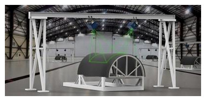
The FARO Tracer projects a template of laser light onto the composite tool, outlining the exact location and orientation of the composite ply materials, and does so in the proper sequence, according to the job’s based ply (layer) schedule. The use of these virtual templates dramatically improves cycle time for very complex layups that take dozens to hundreds of plies.
Furthermore, eliminating the time it takes to build physical templates is crucial to reducing manufacturing costs and time to market.
Using laser projection greatly reduces the painpoints of the ECO process, allowing rapid incorporation of changes (days versus weeks or months). When the CAD model is changed, laser projection changes are uploaded to the computer that controls the projector and the changes are immediately implemented on the next production unit.
Last, but not least, with computer and laser-guided assembly, the possibility of having defects during the layup process is greatly reduced because laser-guided assembly solutions such as the Tracer ensure the highest production quality level, regardless of the experience and the skills of the personnel in the various shifts.
Laser projection technology also provides valuable assistance for advanced/automated fiber placement (AFP) machines. Automated fiber placement machines automatically place fiber onto a tool. In particular, they are used to place fiber in the correct orientation, speeding up the layup process: Traditionally, manufacturers checked fiber angles using hand tools. However, this is time-consuming and labor-intensive and stops production.
Laser projection technology is a fast method of verifying ply orientation. By adopting a laser projector solution, fiber angles can be visually verified during the projection process: The Tracer Laser Projector projects the desired line (fiber angle line) and an operator visually checks using the projected line as a guide and a protractor.
Laser projection also allows the hand layup of ply’s less than the AFP’s minimum course length.
This way, laser projection technology reduces time and labor to check fiber angles: No physical tools (other than a protractor) are required to check fiber angle and fiber angle verification is independent of the AFP machine (Independent Verification).
Get in touch with a FARO representative to learn more here: www.faro.com