
Surface Profile Tolerances
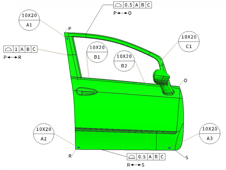
Figure 1. Car door with surface profile tolerances to ensure optimal assembly (Click on the image to enlarge.) Image courtesy of FARO

A surface profile tolerance zone is a three-dimensional volume establishing permissible boundaries of feature(s) of a part. A surface profile tolerance can be used to define a tolerance zone to control combinations of size, form, orientation and location of a feature relative to true profile. For additional information about profile tolerances, please refer to the section 8 of the ASME Y14.5-2009 standard [1]. In Figure 1, we can observe the car door part located through datum targets with surface profile tolerances. In the next sections, we shall analyze these tolerances further to better understand their functions.
Surface Profile Tolerance along the Left Side of the Door
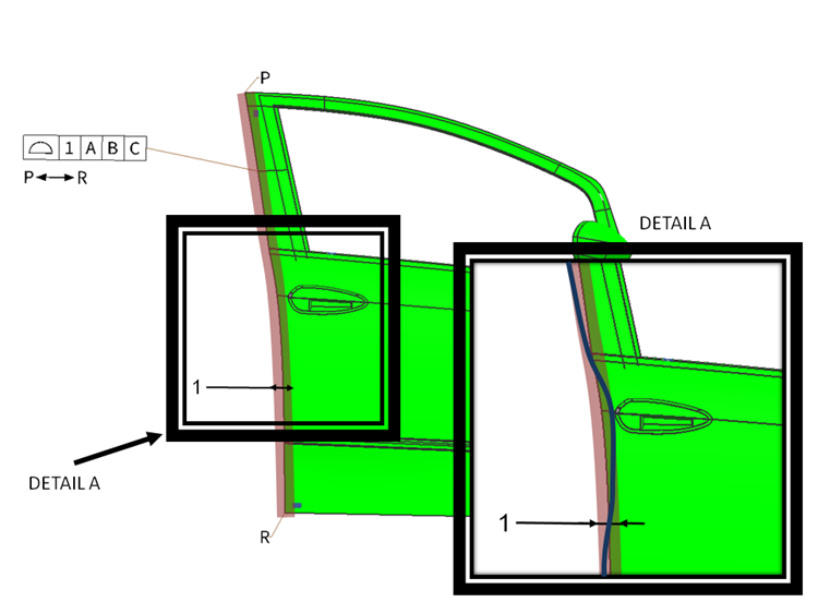
Figure 2. Surface profile tolerance zone between points P and R (Along the left side of the door) defined by the red zone. In Detail View, a close-up showing the actual profile in dark blue. (Click on the image to enlarge.) Image courtesy of FARO
As shown in Figure 2, the surface profile tolerance zone between points P and R (along the left side of the door) must lie with the profile boundaries 1 mm apart (defined by the red zone) and equally disposed about the true profile (0.5 mm on each side). Thus, the feature must be located within the tolerance zone of 1 mm, relative to the datum reference frame ABC. In Detail View, we can observe the actual profile of the door (in dark blue) staying within these boundaries.
Surface Profile Tolerance along the Top and Bottom Sides of the Door
Surface profile tolerance zones on other edges of the door follow the same logic applied above.
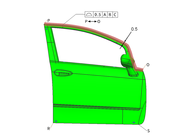
Figure 3. Surface profile tolerance zone between points P and O (Along the top side of the door) (Click on the image to enlarge.) Image courtesy of FARO
As shown in Figure 3, the surface profile tolerance zone between points P and O (along the top side of the door) must lie with the profile boundaries 0.5 mm apart (defined by the red zone) and equally disposed about the true profile (0.25 mm on each side).
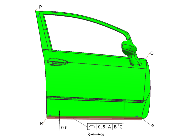
Figure 4. Surface profile tolerance zone between points R and S (Along the bottom side of the door) (Click on the image to enlarge.) Image courtesy of FARO
Lastly, in Figure 4, the surface profile tolerance zone between points R and S (along the bottom side of the door) must lie with the profile boundaries 0.5 mm apart (defined by the red zone) and equally disposed about the true profile (0.25 mm on each side).
Get in touch with a FARO representative to learn more here: www.faro.com
References
ASME Y 14.5-2009, Dimensioning and Tolerancing. New York: American Society of Mechanical Engineers.