
Nondestructive testing of large components can be time consuming and requires several people to work quickly to minimize the impact of testing on the large component manufacturing process. Because the current methods rely on a manual inspection process, it is inefficient and expensive.
One application that illustrates these challenges is the inspection of wind turbine blades during manufacturing. Two areas of the blade that require particular attention are the spar caps and shear web bonding, and both areas are inspected using ultrasonic testing (UT).
Inspecting Spar Caps and Shear Web Bonding
Inspecting the blade’s spar caps and shear web bonding is critical for its long-term reliability. The inspection is typically carried out manually using an ultrasonic probe and flaw detector. A trained operator moves the probe within the region of interest while assessing the live A-scan signal to look for potential flaws. This takes a long time, requires multiple trained operators, and offers almost no traceability or possibility to further analyze the data after it’s acquired.
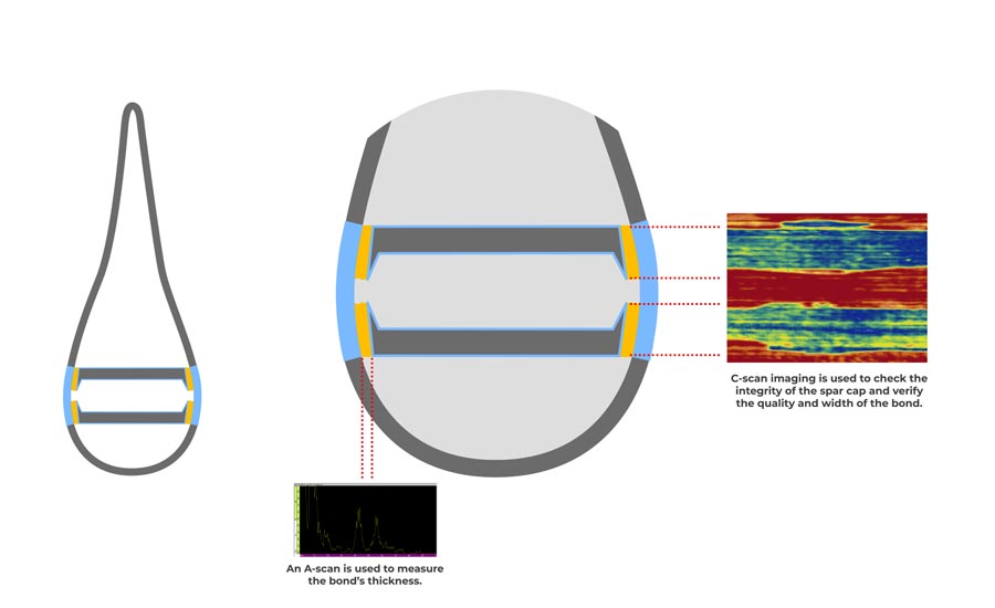
Figure 1. A diagram showing the inspection points for shear web bonding. Photo Source: Olympus (Click on the image to enlarge.)
This inspection can also be carried out using a manual or motorized scanner. The advantage of using a scanner is the ability to acquire encoded data (C-scan), which offers both traceability and post-inspection analysis. However, it’s still slow and there are many constraints; for example, the inspector must move the scanner along the blade and position it correctly to acquire accurate, repeatable data.
Once the inspection data have been collected, they need to be analyzed. And if there are any doubts or questions, one or more re-scans may be required, adding even more time to the process and delaying the blade’s release for shipment.
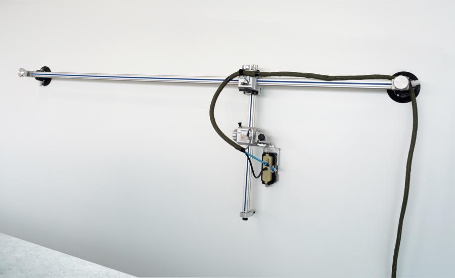
Figure 2. An example of a manual encoded scanner on a wind blade. Photo Source: Olympus (Click on the image to enlarge.)
For any manual inspection method, it’s also important to consider the variability of skill between different inspectors as a critical factor. For spar cap and shear web bonding specifically, the difficulty involved in reaching high areas of interest on the blade, often requiring a mobile work platform, is also a complicating factor.
Automated Wind Blade Inspection
With the advancements brought about by Industry 4.0, it is now possible to solve the inspection challenges discussed above to optimize and improve the wind blade manufacturing workflow. Inspection technology providers are developing inspection systems, using latest digital technologies, to automate wind blade inspection. Below, I discuss one such system that has recently been deployed.
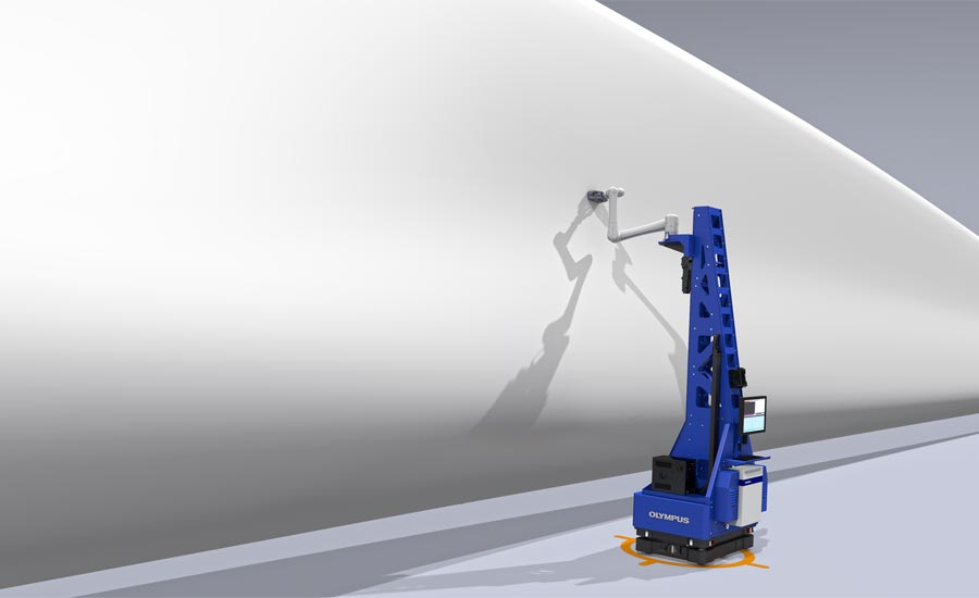
Figure 3. An example of an autonomous inspection system on a wind blade. Photo Source: Olympus (Click on the image to enlarge.)
In this inspection system, a collaborative robot (cobot) is mounted on an autonomous guided vehicle (AGV). The goal is to inspect the different regions of interest on the blade without human intervention except for selecting the blade model to be inspected and pushing the ‘start inspection sequence’ button.
An autonomous inspection is possible thanks to the system’s global architecture that enables each component to communicate with each other. A global interface manages the communication between different elements of the system. Thus, this interface is the brain of the system, synchronizing and driving the AGV, the cobot, a vertical axis to move the cobot up and down, a water system (for UT probe couplant), and an ultrasonic acquisition unit for the completion of fully automated and autonomous inspection of the blade.
How the System Works
The AGV can map the workshop where the blade is inspected, enabling it to learn its working environment and move autonomously within it. Physical targets are used to define the start and end positions of the inspection. At least two targets are needed, one at the root and one at the tip of the blade. The targets have a specific V shape to allow the AGV to accurately and repeatedly dock with it.
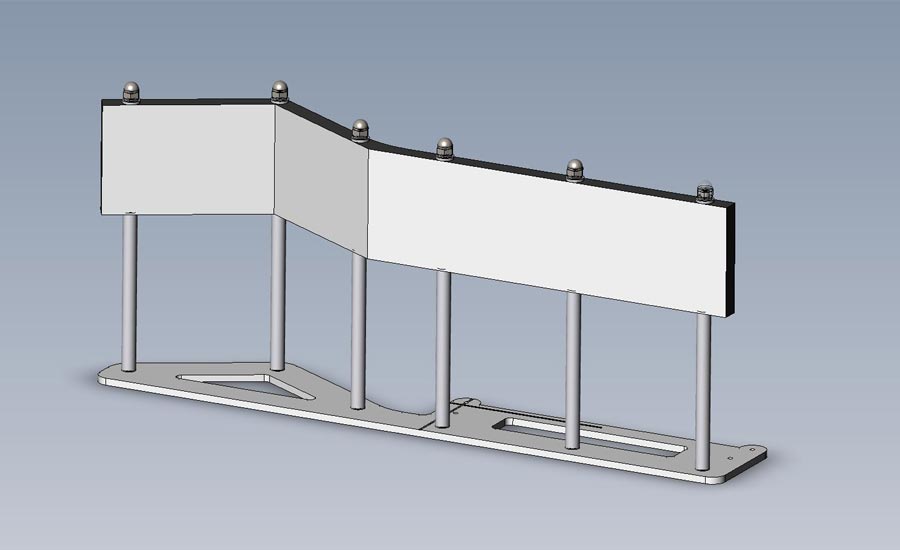
Figure 4. An AGV positioning target. Photo Source: Olympus (Click on the image to enlarge.)
By default, a third target is embedded in the AGV docking station (DS). The DS is the AGV’s home base and where it recharges its batteries. Once the operator launches the inspection sequence, the system moves from its DS to the starting target, autonomously defining the best path to reach it based on the map and taking into account unexpected obstacles. Normally the AGV uses the shortest path to go from the DS to the defined target, but if something is blocking this path the AGV will try to go around. If that’s not possible, it will define a new path using the learned map.
Once docked to the target, the system aligns itself to the blade span using the cobot arm to sense the blade surface and calculate the correct angle to get the AGV aligned with the blade. Then the AGV and cobot arm coordinate their movements to perform a raster scan of the region of interest, typically the lower and upper spar caps and webs of the blade. The cobot arm’s six joints allow precise positioning of the UT probe on the surface and help ensure the constant pressure required for high-resolution, high-quality C-scan inspection data.
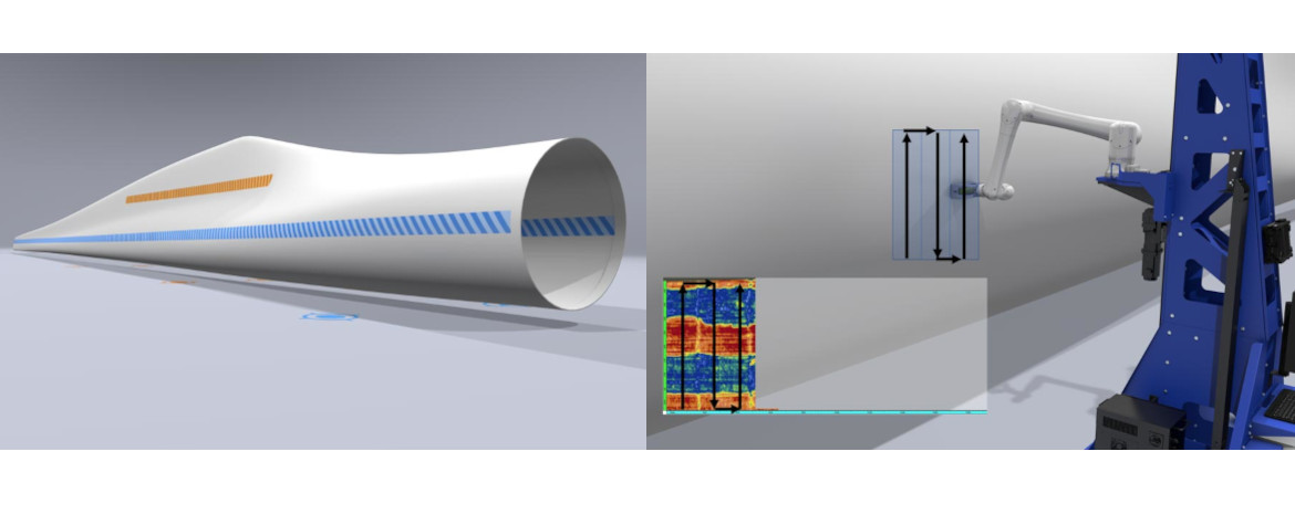
Figure 5. Region of interest with an example of a raster scan (left) and an automated inspection system performing the raster scan on the blade with collected data (right). Photo Source: Olympus (Click on the image to enlarge.)
While each region of interest is being scanned, the system uses real-time positioning information from the cobot to guide the AGV. Based on the extension of the cobot arm, the system can sense which direction the AGV should move and then correct its trajectory to follow the blade curvature along the span. This allows the system to move parallel to the complex shape of the blade without the need to teach the system by, for example, programming it with a CAD drawing of the blade.
The system also uses ultrasonic information to track the spar cap position and adapt the raster scan to this position. This allows the system to follow the position and slope of the spar caps without the need to program their position in advance.
These features enable the system to be self-adapting and self-learning, eliminating the need for time-consuming programming.
Figure 6 illustrates the complete inspection sequence, including a calibration check step using a block located near the docking station. The check block has its own target. Once the operator launches the inspection sequence, the system moves (1) to the first target (T1), self-aligns to the check block, and scans it (2). The system then moves (3) to the root position target (T2), docks with it, and self-aligns to the blade span. The system scans (4) the web and spar cap on the first side of the blade. At the end of the area of interest, the system stops the scan and moves (5) to the other side of the blade to dock with the tip positioning target (T3) where it then self-aligns with the blade span. The system then scans (6) the web and spar cap on the other side of the blade. When the system reaches the predefined end position of the area of interest, the scan stops, the cobot’s arm returns to its home position, and the AGV moves (7) back to its docking station.
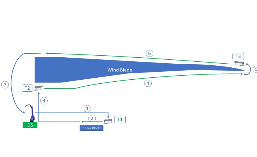
Figure 6. The complete wind blade inspection process using an autonomous system. Photo Source: Olympus (Click on the image to enlarge.)
In addition to executing the automated sequence just described, the system simultaneously manages safety during the inspection sequence thanks to a series of cameras located on the AGV. Several zones can be defined, such as a warning zone around the system so that if an operator or obstacle enters the zone, the system will reduce the AGV movement and cobot speed by half. A safety zone can also be designated that will cause the system to stop completely if anything enters it.
The Future of Wind Turbine Blade Inspection
The autonomous inspection system discussed here combines the advances of Industry 4.0 with established nondestructive ultrasonic testing technology. The result is an automated solution that can learn and adapt both to its working environment and the part being inspected. It provides highly repeatable and accurate data that improves the speed of analysis, reducing the overall inspection time and making the blade manufacturing process more efficient.
In addition to these advantages, the system is cloud enabled so that users can upload inspection data files on the fly. Captured data is uploaded to the cloud and can be analyzed as soon as it has been acquired. This cloud connectivity also enables the data to be analyzed by users working in remote locations for better mutualization and resource efficiency.
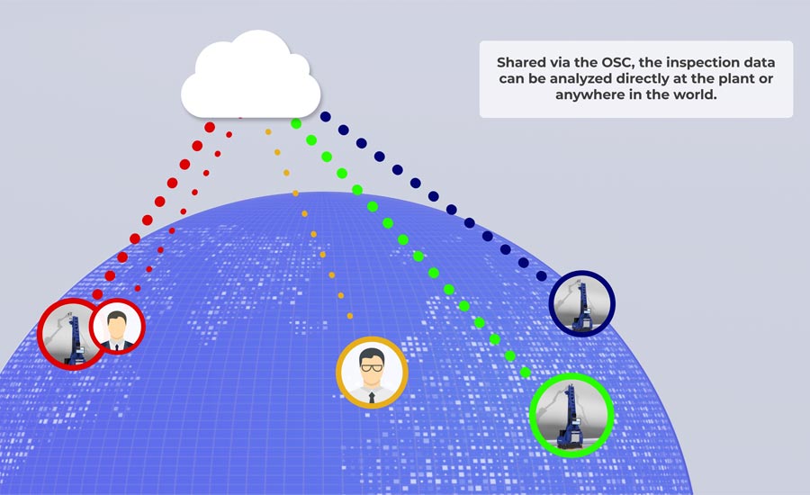
Figure 7. Data are collected all over the world and uploaded to the cloud for instant access from anywhere. Photo Source: Olympus (Click on the image to enlarge.)
While this example is specific to wind blade inspection, this system is easily adaptable to other large component manufacturing applications that utilize nondestructive testing. Combining tried and true inspection technology with the latest innovations in robotics and self-learning will continue to produce novel systems that streamline inspection applications.


