
You may think GD&T is too complicated or difficult for your work. However, there’s a reason it’s a top search term for us month after month.
Let’s take a closer look at GD&T, or Geometric Dimensioning & Tolerancing. GD&T can be viewed as a language, where designers express the tolerances or requirements on the parts or assemblies to the people who build those parts. The requirements are there for people to understand the intentions better. The designers will encode GD&T on a drawing and the others decode the information.

Understanding GD&T is very important on both sides. From the designer’s perspective, understanding it completely will help utilize that language to its best. From the machinist’s side, it allows you to manufacture a part that will fit the tolerances prescribed by the GD&T. If you understand GD&T, including its intricacies (ex. bonus tolerances), you will be able to leverage what’s permitted to your advantage and manufacture parts at lower costs.
How does GD&T affect the machining process?
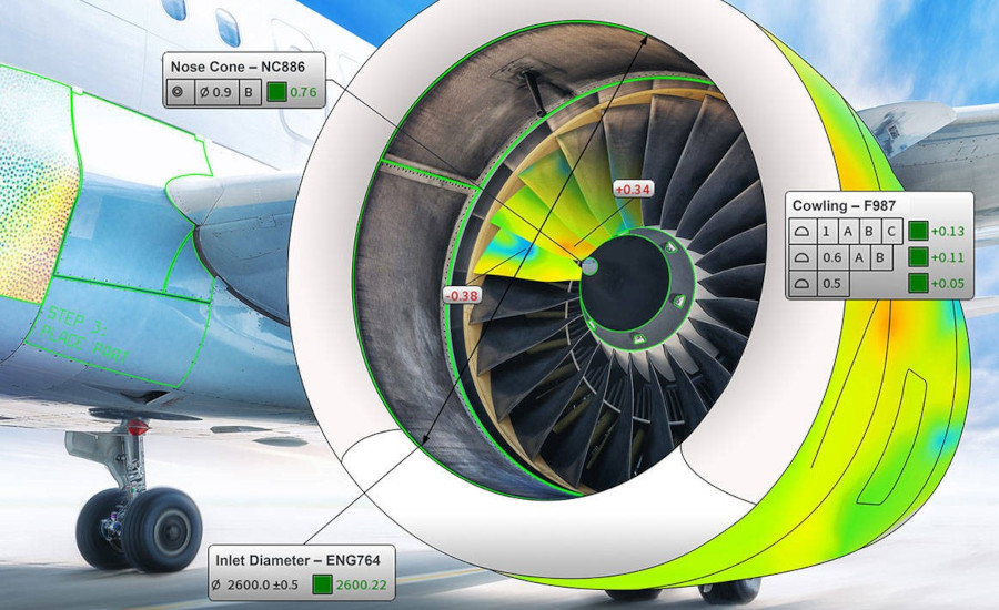
Click on the image to enlarge. Image courtesy of FARO
Like any language, you need to understand it fully for best results. Think of geometry or mathematics. If you don’t understand it, you might think of it just as symbols. This could result in a part that might not meet the tolerances. Alternatively, you might produce a better part compared to its tolerance, meaning that it will cost you more. The goal is not to make the perfect part; the goal is to make a part meeting the tolerances.
GD&T is often seen as difficult to learn but spending time on the basics can help. In addition, software and additional tools can help you figure out how to work with GD&T. It helps to know the basics—the more you know, the better—but tools can help as well.
With today’s software, you don’t need to have a complete understanding of GD&T. For example, you can look at the CAD model of a part, import the model, and the GD&T (often referred as PMI – Product Manufacturing Information or FT&A – Feature Tolerancing & Annotations) could be embedded there. Then, as you’re performing the inspection with probing or scanning devices and taking those measurements, with the correct software, the GD&T automatically would be evaluated for you. This would include simple tolerances like flatness, linearity, and positional tolerancing, but also the more advanced ones, like material condition modifiers, composite tolerances or datums. All of these tolerances can be evaluated using modern software – no more need to rely on in-house Excel spreadsheets or dedicated GD&T experts.
Technology has advanced to the point that anyone can scan or measure the part and you would understand if it was good or bad. Instead of scrapping a part completely, you would understand what to fix.
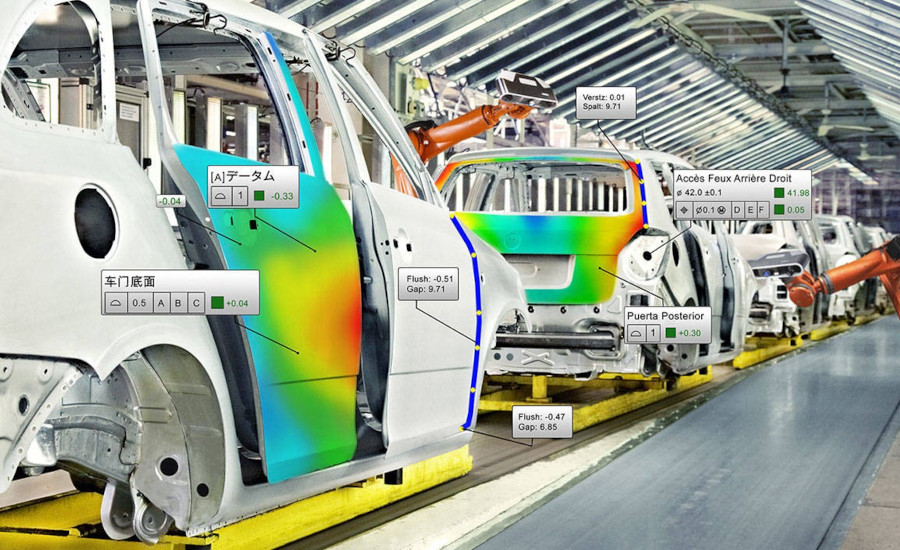
What Manufacturers Should Know for GD&T

Click on the image to enlarge. Image courtesy of FARO
Technologies are available to help you through the process, specifically software, which has come a long way. Even five to seven years ago, software wasn’t where we are right now with GD&T evaluation. In the past, GD&T relied a lot on the inspector’s knowledge, and they had to understand it fully to know if a part was good or bad, which is not where we are today. Now GD&T from multiple software programs is able to evaluate these tolerances, from simple to advanced. The bottom line is that software can really help.
With the increased accuracy of scanners, workflows are also improved. When software is able to cope with large amounts of data, operators can scan a part and perform evaluation almost at the same time. This workflow allows for a more accurate, faster, and therefore cheaper, approach. You’re able to catch issues faster and, saving costs on scrap and rework.
Perhaps you’ve seen this scenario or experienced it yourself. You buy a software with a perpetual license and didn’t keep it up to date, so you may be using software that’s five years old (or even older!). Updating this can really solve some of those struggles.
Consider a quality inspector measuring parts who must transfer some of the measurements to an Excel file to perform GD&T evaluation that the software wasn’t capable of. During that time, production continues so you might be producing bad parts as you are measuring. By working in a tighter and faster loop, you save time.
GD&T bonus tolerances can give you a hidden advantage. For example, if there is a hole you need to manufacture, and it has a positional tolerance specified at MMC (Maximum Material Condition) – with a M symbol. If the hole’s location is slightly off, since the tolerance is specified at MMC (when the hole is at the maximum material condition, i.e. smallest hole), increasing the hole size by drilling it bigger can make it pass the tolerance. Understanding GD&T in this case can help you save the part with minimal rework.
Potential GD&T Problems
Click on the image to enlarge. Image courtesy of FARO
As you might expect, misusing a language can lead to problems. In the case of GD&T, misinterpreting tolerances can lead to lost time or scrap. Scrap might be created because someone didn’t understand GD&T properly. Perhaps they found a false positive or false negative based on faulty knowledge of GD&T. Maybe it was a misunderstanding of a specific GD&T tolerance made them throw away a good part. And if you accept a bad part based on a GD&T misinterpretation, this can lead to problems down the road, as parts don’t fit correctly or mate properly at your customer’s assembly site. Production stops and customers get angry, which could lead to losing a customer, all because someone didn’t understand GD&T.
So how to make sure you understand GD&T? Investing in GD&T classes would be a good step, but investing in updated tools could definitely help as well.
When we compare GD&T vs. traditional tolerancing (ex. linear and angular dimensions), people tend to think GD&T is more expensive, “complexifying” the part, but actually, it can make it cheaper, both from a design and machinist perspective. For designers, GD&T tolerances can reduce cost because it provides more leeway to the machinist to manufacture your part. Instead of asking you need a part two inches long, perhaps you would encode that you need to have two surfaces parallel for two inches. That two inches dimension could have a looser tolerance. Seeing it in a drawing can help decrease the cost of the part being machined, as the machinist does not have to make sure part perfectly at two inches, but the two surface just parallel.
Misconceptions about GD&T could increase the price a supplier would quote. If they understood the GD&T, they would be able to provide a more accurate quote. Then they could offer a better price to the customer and companies who didn’t, would quote higher, missing an opportunity.
If you’re able to understand GD&T completely, it makes your part cheaper to produce. While it may seem daunting, it is well worth learning. And today, the right tools can also make the job easier than ever.
Get in touch with a FARO representative to learn more here: www.faro.com