Many new industries are employing 3D scanning not only to create 3D models of parts or products for reverse engineering but also to explore the composition and rapid production of ready-to-use parts via 3D printing.
Even as the tools for extracting information from objects grow more sophisticated, there is still a lack of consensus as to what exactly constitutes “reverse engineering.” In the simplest terms, reverse engineering is the process of measuring precise 3D dimensions of an existing object and converting that information to a 3D CAD model.
Reverse engineering’s steady growth is due to a number of factors. Companies are still using equipment from suppliers that are no longer in business or that have stopped supporting earlier models. When that equipment needs replacement components, reverse engineering offers a way to recreate those parts. The military has some of the largest needs in this regard because they are often making do with aircraft and machinery that has passed its original use-of-life estimate and is lacking specific technical data. Reverse engineering parts and systems enable aircraft to keep flying or machines to keep running.
In a similar scenario (recently evident in the fracking industry), companies have sometimes been required to purchase specific parts, which were patented, and those patents have now expired. Low-cost replacement parts can be generated through reverse engineering.
Yet another factor in the growth of reverse engineering has been the high number of mergers and acquisitions over the past decade. The acquiring company often finds that smaller companies have not updated their CAD drawings to match tooling or that many of the parts being manufactured were made in a pre-CAD period. Top companies want to keep tight process control, which means having accurate CAD models within their product lifecycle management system.
Plants and factories are also now utilizing larger-scale 3D scanning. Many petro chemical manufacturing plants stacks only shut down for three months every seven years. For every day they go past the 90-day downtime mark the cost is several million dollars. By utilizing different scanning technology they can model existing structures/piping/equipment. This saves time and money by allowing the supplier to know how they are going to move multi-ton equipment to upper floors and ensures that when new equipment is in place the existing piping will attach correctly.
Architects are also starting to embrace reverse engineering of structures. When purchasing older buildings to be renovated or a new shop in a mall, having precise dimensions of windows, doors, HVAC, piping saves tremendous time and ensures minimal rework or expensive misfits.
Purchasing
When thinking about 3D scanning purchase options it is important to ascertain your reverse engineering needs. More than one measurement tool may be needed in your tool box, as well as a knowledgeable staff to operate the equipment and software.
Typical prices for 3D scanners range from $10,000 to $500,000. The pricing of a product is closely tied to the accuracy of the data it collects. Verifying accuracy claims of scanning systems can be challenging. One way to accomplish this is to have a reference part that has been measured on a CMM or other reliable source. Data about the part obtained from other tools can then be compared with the established measurement for accuracy.
Outsourcing
If you decide to outsource, you’ll want to obtain quotes from one or more service providers. One way you can make the quoting process easier is to know why a part needs to be reverse engineered. Knowing how the data will be used will help your provider determine: 1. the specific information that is needed and 2. the best tool for obtaining it. Some other things to consider before seeking quotes: How accurate does the scan need to be? If your part is a gas turbine blade then you are going to need sub .001” accuracy. If it is a consumer product less accuracy of greater than .001” is probably fine. A service provider with experienced engineers should be able to guide you and make recommendations.
Other questions to ask potential service providers: How many years of experience do they have? Can services be performed at the client’s site? Have they completed similar projects in your industry? What services do they provide beyond gathering the measurement data? For example, it is becoming more common for clients to want 2D drawings and full metallurgical information in addition to 3D CAD models. Does your provider include that information in their services package?
The final important question is: what file format is required? Items being duplicated exactly can be achieved with an IGES, STEP, or Parasolid model. If the model needs to be easily modified a native CAD model with full feature tree will be a better option. Determining the file format ahead of time should make the quoting experience easier.
The Four Steps of Reverse Engineering
Reverse engineering can be broken down to four steps:
- Measurement,
- Processing
- Modeling,
- Validation.
Measurement
Data collection can be achieved with both contact and noncontact methods. A 3D non-contact scanner collects data at a rate of several thousand points per second to record the size and shape of an object. As it moves, the scanner creates a “point cloud” of geometric samples from the object’s surface, which defines its various surface shapes, contours and dimensions. The point cloud can then be converted to a CAD-friendly format to create a 3D replication of the object.
You will likely want to opt for a high-speed, noncontact scanner if the product you’re measuring: 1) has a complex geometry and/or the entire surface area needs to be measured, 2) is fragile or prone to damage, or 3) has a shape might be altered by contact, as in the case of soft or compressible objects. If you need to measure the internal features on a closed product, then a CT scan is required.
Below are some of the major categories of noncontact 3D scanning technologies:
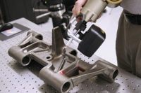
Handheld laser scanning involves a portable, noncontact laser scanning device. A handheld scanner can capture an object’s 3D coordinates, or data points, rapidly and with a high degree
of resolution and accuracy. It uses a laser stripe sensor, mounted on a portable localizer to capture lines of points as it sweeps across the surface. This quickly builds into a cloud of points defining the complete surface of the object being scanned. One advantage to these scanners is their versatility—a handheld scanner is capable of capturing 3D measurements from objects of almost any size or shape in almost any environment
Computed Tomography (CT) scanning utilizes X-rays to produce 3D representations of both internal and external surfaces. It is fast, accurate, non-invasive and nondestructive. Its ability to capture internal geometry makes CT scanning a good choice when measurement requirements exceed the capabilities of line of sight scanning technology.
Long Range scanners are known as time-of-flight scanners and laser phase shift systems. Long-Range scanning is used when large-scale data capture is needed as in the case of factories, power plants, buildings, or roads and bridges. By rotating the laser and sensor (usually via a mirror), the scanner can scan up to a full 360 degrees around itself. By modulating the power of the laser beam, the scanner compares the phase of the laser being sent out and then returned to the sensor, creating measurements which are extremely precise.
Structured Light Scanning uses white or blue light to create a series of reference patterns on an object. With each shot at different angles to the object being measured, the scanner captures data points in greater density and then stitches the different patches together, usually with pre-mounted stickers. Since the data points are denser and closer together, the object’s geometry is captured in greater detail. To stitch together multiple scans, reference stickers are often used or photogrammetry is employed. This type of scanning is a good choice for measuring intricate, detailed parts.
Processing
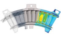
Noncontact scanning produces point clouds of data, which need to be converted into a form compatible with CAD software. There are specialized reverse engineering software programs to convert large point clouds into a triangulated STL (StereoLithography) polygonal file, in which the data is seen as a raw triangulated surface mesh. This STL file is the format used by rapid prototyping systems to grow parts
Modeling and Validating
A solid model will be constructed from the STL data by using standard tools such as extrudes, lofts, sweeps, and revolves. A solid model allows you to see your part in real, 3D space and view it from any angle.
If your application requires a true parametric model (a model that is fully modifiable in CAD software), the model will need to be completed in SolidWorks, Inventor, CATIA, NX, or Pro E/CREO. A parametric model contains a full feature tree, which means that you can make changes to any feature of the model and every related dimension will update accordingly.
The use of 3D scanning for reverse engineering continues to grow for a very good reason: it provides an unprecedented opportunity for excellence. In the constant journey to improved quality, earlier measurement tools were paper maps—3D scanning is GPS.


