Reverse Engineering: A Basic How-To
The advancements in technology over the last 20 years have been amazing.
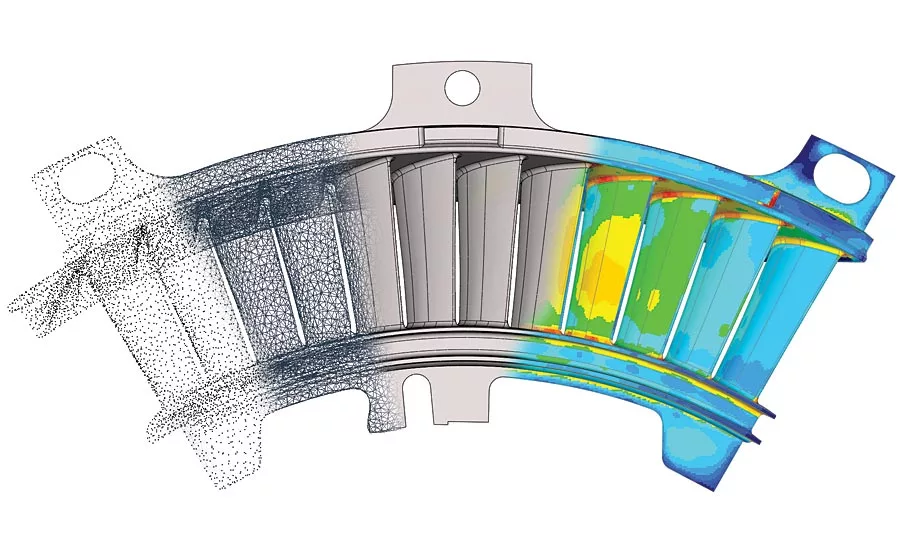
This blade assembly image shows the start-to-finish full scan data capture to parametric CAD model.
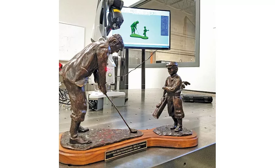
This 3D laser scan of a trophy was used to make new replicas.
Step 1: Determine Intent
How will this image be used? Do I anticipate any changes? What are your tolerance requirements? All these questions are paramount in determining the successful path of the data output and each are mutually exclusive of one another.
Why do I care how it’s being used? After being in the 3D scanning service industry for over 18 years, I find significant value in this simple question. Here’s why. When approaching a project of any magnitude, the ideal goal is to find the cleanest, clearest path with an optimal desired result. Not knowing the intended output can send a service tech down a long, inefficient path. Here is a scenario I encounter on a regular basis. Customer: “I need to scan an entire engine for a vehicle with CAD output.” At face value, I can jump to the conclusion that they need every nook and cranny digitally captured by any medium of my choosing and I can spend several weeks meticulously creating detailed models of starter motors, cooling lines and complex engine block castings. Ninety-nine percent of the time, that is not necessary. After asking that simple question—how will this be used?—a simple volumetric representation is all that is needed to determine fit and clearances. This can be accomplished quickly and efficiently, using simplified scanning techniques and rapid solid modeling.
Why do I care if the customer anticipates changes? Anticipated changes drive the method of creation. Another common question I receive from customers is, “I need a Parametric IGES or STEP file.” This is a contradiction. Parametric CAD models contain design intent, a structured combination of prismatic 3D features driven by specific dimensions. An IGES or STEP output is a stripped version of that parametric 3D CAD model, typically represented by that outside “skin” of the CAD surface, allowing users to share 3D data between multiple platforms that do not share a common internal language. So, knowing what changes may be needed is very important. A user can now design a part to make those anticipated areas easier to modify without fighting unwieldy surfaces, fillets or draft in the completed CAD model. Or, in my example above involving an engine, there is no plan to modify that data, only to check what fits around it. This can be resolved with a simplified NURBS (Non-Uniform Rational B-Splines) to get a lightweight, volumetric skin to bring in to the customer’s existing CAD design.
Tolerances? The final deliverable should be perfect, right? Wrong. Do you really need this sand casting within .001”? Are you sure you want to see every imperfection in that part? Let’s apply the brakes at this point and back up a bit. Reverse engineering, as mentioned above, is a path. A path with many twists and forks. This is one of those forks. During the process, tolerances can be managed through use of the correct hardware and software in the hands of a skilled tradesman. Expectations, on the other hand, are still a bit of a slippery slope. Back to the sand casting example mentioned earlier, this is a common request. Modern scanning hardware possesses the ability to capture high surface detail sometimes to the detriment or advantage of the process, depending on the previous factors mentioned above. The reason…anticipated changes. If my intent was to create new tooling and develop clean surfaces for machining, then developing it through a traditional CAD workflow makes the most sense. But, this calls for an allowance. An allowance of tolerance. That intended flat surface may not be flat anymore on the physical part. Through 3D scanning and interpreting those surfaces back to a clean CAD model, I have now taken liberties to correct that discrepancy, therefore influencing the deviation on the actual part back to its new digital CAD counterpart. On the flip side, if I am developing something to perhaps grab or hold this part and I need high precision, then back to that prior fork in the road. We can now take a different approach to the modeling output. Similar to our engine example, we can create high precision NURBS output to satisfy those exact surfaces and make certain the part is defined properly.
Step 2: Acquisition
Now that we have the guidelines established for intent, let’s examine our options, based on those choices. As I mentioned earlier, the advancements in technology over the last 20 years have been amazing. Structured light is cleaner, portable arm-based laser scanning is much faster and more accurate, plus the time-of-flight and phase shift (long range) scanners can scan further distances with substantially higher precision. Metrology grade 3D CT (X-ray) scanners are becoming more powerful and financially feasible.
Why Structured Light? Because it’s clean. Clean data yield a cleaner result. Structured light is typically a two-camera, stereo system. The system uses a digital projector to project a fringe pattern onto the surface of the part, thus displacement of the fringe pattern along the part is correlated back into 3D data. These sheets of lights bounced off the part provide a clean and highly accurate digital representation of the part. This clarity is regarded as a high standard in comparison to its counterparts mentioned below. Its only real limitations are translucency/transparency and deep colors opposing the light spectrum of the projected light. Also, both cameras need to see the geometry that is being captured.
Why Portable CMM/Scanning Arms? Speed and flexibility. I think one of the largest improvements has been in the portable CMM industry. Wider laser lines, higher hertz rates for data capture and millions of points captured in seconds. These pieces allow users to adapt quickly from being set up in a controlled lab environment to quickly packing it up and mounting it on a machine on the shop floor to resolve an issue. Data from these units are captured via laser and its ability to adapt to different surface colors and finishes has become highly advanced in recent years. Chrome and deep blacks were always the nemesis, but those days are fading away. Quickly. With tolerances getting close to matching those to structured light, they are taking a good hold on the market and are becoming a dominant force and a valuable tool in reverse engineering. Current limitations are set only by the length of the portable arm, with multiple setups being required for part sizes beyond the arm’s reach.
Why Long Range? Do you need to map out a building? Do you need to reverse engineer the outside of a 747? If so, this is the perfect tool. With the ability to scan geometry hundreds of meters away within a reasonable tolerance, long range scanning is the right application. These tools are sending out a laser beam with high precision and recording the surface it bounces off back into digital 3D data. That data can be combined with high-res imagery to provide 3D visualization of the objects, areas or spaces being scanned.
Why CT (X-ray)? Visualizing internal data is typically lumped into the category of inspection. But with 3D X-ray machines becoming more powerful to see inside of dense materials such as steel, extracting those internals can prove valuable. Internal passages that were created with a complex network of sand cores in a foundry process can be seen to correctly validate clearances when recreating a new part. CT also eliminates blindspots, allowing designers to model complex sculptural surfaces with precision and assumptions in filling in missing geometry from conventional scanning methods.
Step 3: Processing
Now we know what the intention is and how we are acquiring data, so what do we do with it? Today’s processing is a bit of a broad spectrum, but I would like to highlight some guidelines to once again lead us down a clear path.
Garbage in, garbage out. With the wide variety of scanners mentioned above comes a bit of responsibility. Know your hardware. Know its capabilities, know its limitations. At this point, we know how it’s being used, how accurate it needs to be and what methods we need to use to get there. Taking small shortcuts in the scanning process leads to time-consuming editing when processing 3D data. For instance, not taking an additional scan to capture the bottom of a groove or hole leads to a lot of assumptions when interpreting the scan data into a polygonal mesh. One additional five-second scan could save hours of work. Clean data input streamlines the processing.
3D point cloud, now what? I now have millions of points that cleanly represent the part, so let’s go to the next step. The common next step is converting the XYZ 3D data points into a polygon model. Simply put, the software connects the dots with a series of triangles to create a representative skin. There are various tools that can accomplish this goal. Most hardware suppliers provide this direct output from their scanners, others rely on third party software to run the calculations. From here, the world is your oyster, so to speak. There are many software packages that allow you to manipulate the data, including smoothing out imperfections, closing small or even absurdly large holes within a reasonable assumed precision. The ability to quickly edit out pesky clamps or fixtures holding the parts during scanning is amazing. This step sets the pace for the next round of modeling.
Conversion. My polygon data, commonly referred to as an STL, is ready to go. Intent? Check! Now let’s convert this to a useable format with the necessary parameters to get what we need out of it. Here, we come to our final fork in the road, as defined earlier by our intent. This is also another part of this process that has dramatically improved in the last 10 years. The ability to get from physical part to 3D data is 5:1, maybe more. Gone are the days of scanning a part, bringing a low-resolution version into a CAD package, cutting cross sections, converting those to complex sketches and then generating 3D features off those sketches. Today, there are software packages that can handle scanning directly into their software, converting large data sets to high-resolution mesh data and generating native parametric CAD features, all in one package, thereby shaving days off the process and achieving a much better result. Also, the ability to generate NURBS or “As-Is” surface data with extremely high precision has been a dramatic improvement. With complex algorithms able to solve data sets with complex surface geometry with a single button push, the process continues to get faster and faster, as well as more accurate. The best of both worlds.
Validation. Now that we have two pieces, 3D scan data and the intended CAD model, let’s wrap up the process. Before I throw this over the wall to manufacturing or whatever downstream process required, I need to check my work. Another improvement that continues to excel is the ability to validate data. Validation, used here, is the ability to show deviation of the scanned object back to the CAD model being developed. This deviation is represented typically by a color map, with each color representing the 3D distance each point varies from its CAD model counterpart. Once this evaluation is complete and meets the expectations determined, the CAD model is ready to be delivered.
I hope this short how-to sheds some light on your protocols and processes in scanning for reverse engineering.
Looking for a reprint of this article?
From high-res PDFs to custom plaques, order your copy today!


