Reverse engineering as a term is adopted by many industry subsets. From genetics, computer code, complex PCBs (printed circuit boards), and even military espionage. In this article, we are specifically relating to a metrology-driven process steered by high-precision 3D data acquisition tools. These processes are paramount to the automotive, aerospace, and medical industries. These industries rely on the process so much, they help drive the hardware and software to improve quality and efficiency of the process.
What is reverse engineering in the context of the metrology world? Simply, the process of taking a tangible object, and converting it into a digital format. Complexly, there are a variety of paths to be taken to accomplish this goal. It starts with a data acquisition process, commonly a collection of millions of points in 3D space through an optical source. Those optical sources are comprised of lasers or structured light reflecting off the object to be measured and reporting back 3D values through a singular, or multiple arrays of sensors. The quality of the digital input traditionally correlates to the hardware being used. This critical step sets up the success of the digital reverse engineering process. Garbage in, garbage out. Once the 3D volumetric data is captured, the heavy lifting begins in the software. The next step is leveraging software to convert that 3D point cloud into a usable format for its next step in the process, be it additive 3D printing, CNC machining, or just visualization for a complex assembly.
With current software platforms, there are a variety of processes to efficiently move you down those aforementioned ‘paths.’ From simple point cloud-to-mesh conversion, highly accurate NURBS (non-uniform rational b-splines), and dimensionally sketch-driven feature-based models like traditional CAD packages, picking when to use those is a critical step.
Being involved in the metrology service business for over 23 years has provided an interesting series of challenges. Some of those requests are driven by buzzwords or the expectation of easy buttons. As I will now cautiously admit, the ‘easy buttons’ have come a long way with software, but it isn’t always the correct deliverable in the end. One of those valuable components in reverse engineering is when do you go down a certain path. That journey begins by determining the intentions of the final result. This driving question helps define the process all the way back to the data acquisition process. Earlier, there was mention of several different output types: Mesh, NURBS and CAD. Let’s evaluate them individually and cite some examples of use. Mesh data is a tessellated point cloud. The object is scanned, 3D point cloud is generated and a series of algorithms convert that point cloud to a contiguous ‘skin’ of traditionally three-sided polygons.
This process can serve as a lighter-weight representation of the object that was scanned due to the software resolving the redundant 3D points created by the scanner. Think spray painting over the same area multiple times. The paint particles are stacking up on top of each other and eventually, their redundancy is no longer needed to represent that painted surface. The mesh process is consolidating all those points into one simple sheet of polygons, while retaining the accuracy of the original scan. Stripping millions of points down sometimes to thousands of points. This now can be processed through some reverse engineering software to fill small gaps that may be missed by the scanning process, or capping off part of the data that was obstructed from the table it may have been fixtured on. This end result may satisfy the reverse engineering request at this point. It can go direct to print for any additive process; it can be imported into most CAD packages these days (dependent on the amount of polygons as they are traditionally graphic card intensive). This serves the art and history world quite well, for archival and preservation. Some scanning technology even has the capability to capture the color of the object and map that onto the mesh, giving you realistic, digital representations of century-old artifacts in museums, or even a virtual tour of a favorite sneaker.
Returning to the point mentioned earlier regarding the driving scanning process, all the samples mentioned would require ideally near 100% surface capture with the scanner. 3D printing (additive) likes watertight data, no holes, and you don’t want to spin that shoe around on your phone app and see a big chunk of data missing… If the intention of the reverse engineering project is to go through a machining process or to have data in a traditional CAD environment, then there are two options, NURBS or CAD. Both can be used interchangeably in a CAD/CAM machining process, but they are certainly two different animals. NURBS data is a highly accurate representation of the mesh. This process is handled slightly differently in a variety of reverse engineering software, but the end net result is nearly the same.
The process starts with a clean, representative mesh. Again, garbage in, garbage out. A series of curves are mapped onto the surface of the mesh. They constantly are adjusting to the underlying mesh, there is some logic to how those curves are applied with attention paid to critical geometry, think corners or stark directional change in geometry. This is one of those ‘automatic’ functions I traditionally despised, but have conceded that it does quite an impressive job with the current software packages on the market. Once the curve network is established a series of smaller curvature patches fill in that original curve network, then those smaller patches are divided into UV grids, and the final surface result rides along that UV grid structure to create the final part shape.
Here is why it differs from traditional CAD and when it would be used. The curve network is applied regardless of traditional CAD parameters. There are no driving sketches with dimensions or constraints. Depending on the user and the care taken to apply those curves, this process will yield an unbelievably accurate result, with nearly a minimal deviation from the original scan. A common use is salvaging legacy tooling from a foundry or injection molding process, capturing the exact contours of complex geometry that can go direct to CNC tool path for new machining. It is also commonly used on more organic surfaces like human forms or geometry that is hard to replicate using CAD functionality.
I have often steered customers down this path, once learning what the final intentions of the data is. A common example I use is an engine for a car. We get multiple requests for a full CAD model, but if you dig into the need, it is only being used for a virtual fit up or assembly to make sure it clears a cavity or a new part is being designed around it. This NURBS solution provides significant time/cost savings from the original ask. Finally, traditional CAD modeling. This process involves breaking down the mesh into logical components. Sketches are derived from the mesh and used to form extrusions or cuts as the user chisels away until the final shape is achieved.
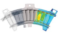
One of the advantages in reverse engineering software is the ability to dynamically ‘check your work’ as the features are created. A tolerance heat map can be applied to capture how far the CAD features deviate from the original scan data. This allows the user to dial in the work until an allowable deviation is achieved. This process is open to interpretation to the user and even presents these sub-paths in this process. The manufacturing process is not perfect, depending on material or process there are many things that can subtly change the shape of the part. Grinding a parting line off of a casting, shrink on a plastic part or even a broken section of a part. This is the opportunity in this process to correct those deviations using logical design principles. A hole measures .505”, probably should be .500”. 2.87 degrees of draft can be corrected to 3 degrees. Conversely, maybe those measured dimensions are critical function of the part, and they can be modeled as-is. This modeling gives you the freedom to make those changes based on the end result needed.
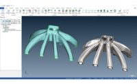
A great example is the ubiquitous fan blade or propeller. Differing from the prior options of Mesh or NURBS, the entire part may not need to be scanned. If you mechanically break down these components, it is simply a circular hub, and a rotational pattern of a blade. One could conclude that all that is required of the scanning process is a simple scan to get enough profile to represent the hub geometry and one blade to pattern around a shared center with the hub. No need to scan the entire part, and risk modeling all the blades and end up with a wonky result. It is implied that this should be a perfect pattern and is usually modeled as such. This dramatically saves scanning time, modeling time and ultimately money.
Where is reverse engineering used? Practically everywhere and in every industry. The process can be used to gain competitive leverage with products, by instead of reinventing the wheel, digitally duplicating it and improving its process. Salvaging centuries old artifacts and digitally reconstructing broken components, similar to the Notre Dame repair efforts. The pattern industry is heavily reliant on capturing legacy wooden pattern, constructed by skilled craftsman. Those accurate, digital copies can now be implemented into modern machine practices to keep the production of components moving forward. Are you ever curious on how cell phone protective covers are available in short order after a new phone model has been released? Reverse engineering.
Why reverse engineering? Why not?


