Test & Inspection
How to Deal with the Difficulties of Microhardness Testing
We’ll cover some of the common problems associated with microhardness testing and address some of the techniques and technologies that can be used to avoid them.
This direct-reading, depth-of-penetration tester uses a conical diamond indenter and 1000gms for the major load. It employs the preliminary load / total load / preliminary load progression comparable to what is used on all Rockwell hardness testing instruments. Source: AMETEK Inc.
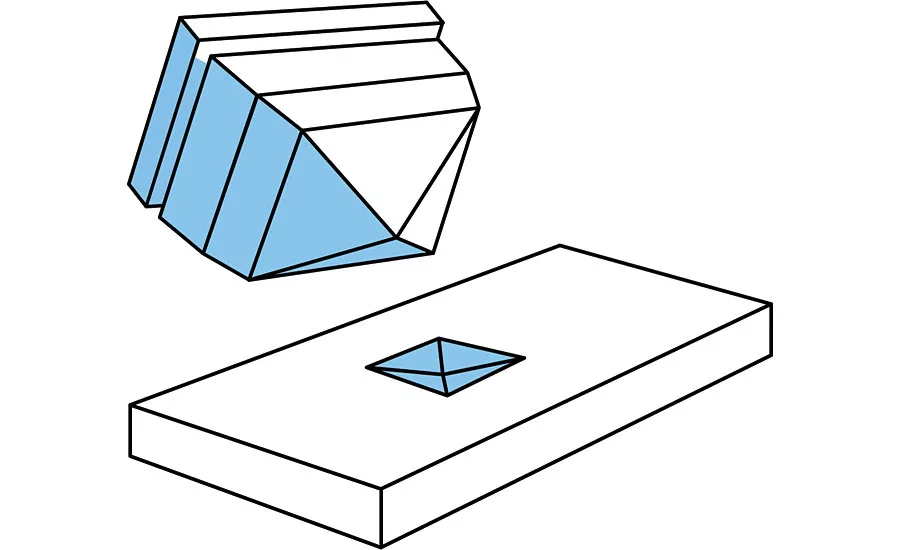
Vickers indenter faces are set at a 136 degree angle from one another. Source: AMETEK Inc.
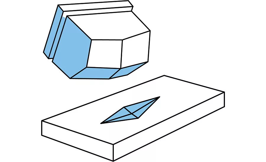
Typical Knoop indenter geometries. Source: AMETEK Inc.
The Vickers and Knoop microhardness testing methods have become invaluable for the testing of a variety of parts, which have what can be referred to as “shallow layer hardness.” Such characteristics as surface hardness, thin cross section, coating hardness, and case depth are measured using the microhardness testing methods. These methods also can be useful for selective testing of particular grains or constituents such as those found in powdered metal parts.
VICKERS, KNOOP, BRINELL AND MICROHARDNESS: WHAT’S THE STORY?
The microhardness indention testing method was developed over time as an outgrowth of the Standard Brinell hardness test. Robert L. Smith and George E. Sandland at Vickers Ltd developed the pyramid diamond indenter in 1921 as an alternative to the Brinell test method to measure smaller areas and higher levels of hardness than where capable with the standard Brinell ball indenters.
The Knoop test was developed by Frederick Knoop and colleagues at the National Bureau of Standards, the current NIST in the United States. The Knoop method uses an extended pyramid with face angles that are 172 degrees for the long edge and 130 degrees for the short edge. Both Vickers and Knoop are defined by the ASTM E384 standard.
TECH TIPS
|
The testers that have been developed for microhardness testing, of course, are much smaller, use lighter loads and due to the very small size of the impressions created have higher magnification optics.
THE DIFFICULTIES OF MICROHARDNESS TESTING
While most microhardness testing is done in quality control or metallurgical laboratories, as opposed to the shop floor like most hardness testing, and operators generally are more highly trained, it is still a test that is difficult to get right. When asked about microhardness testing, most inspectors and production managers describe a process that is complicated, subjective and extremely slow.
Modern Vickers and Knoop hardness testers in themselves are very accurate in applying the test force as well as measuring the size of the impressions. That being said, in most cases, all three of the above negative connotations are deserved, for several reasons. However, advances in computer technology have reduced, if not eliminated, those not-so-kind adjectives.
Microhardness testers are precision instruments. Extremely light forces (typically from 10 to 1,000 grams) must be accurately applied and the resultant impressions—some as small as 10 microns (0.0004”)—must be precisely measured under high magnification. A number of inherent problems arise because of those stringent requirements. Although the specifics of these problems are specific to microhardness testing, the three basic problem types are the same regardless of the hardness testing type used, or to some extent to all testing equipment.
THE THREE BASIC HARDNESS MEASURING PROBLEMS
Typically, testing problems can be separated into three categories—accuracy, repeatability, and correlation—and traced to five main causes—machine, operator, environment, sample preparation, and calibration.
Before discussing the causes, it is important to define the problems:
- Accuracy: The ability of the instrument to read in a linear fashion on recognized hardness standards (certified test blocks), and its ability to transfer this accuracy onto test specimens.
- Repeatability: A measurement of how well the instrument is able to duplicate its results on recognized hardness standards.
- Correlation: The ability of the instrument to produce results similar to those produced by another “properly calibrated” instrument or the ability of two operators to measure the same part, using the same machine and to achieve similar results.
With an understanding of those problems, we can better relate to their causes. With the operator being the unrivaled source of error in traditional optical microhardness testing, that particular cause is what we will focus on first.
REDUCING OPERATOR ERROR
The unrivaled source of error in traditional optical microhardness testing is the error induced by the operator. This gets compounded when surface preparation is poor and when the “heat of the battle” is on. The mundane nature of measuring multiple impressions also contributes to fatigue and subsequent errors.
So, how do we then minimize this effect? In sporadic testing situations, it is important to ensure that the operator is properly trained, that he or she has the proper tools to prepare the test surface, that the instrument is in calibrated and in proper working condition, and that the operator has time to do the job properly. With a conscientious operator, error will be minimized.
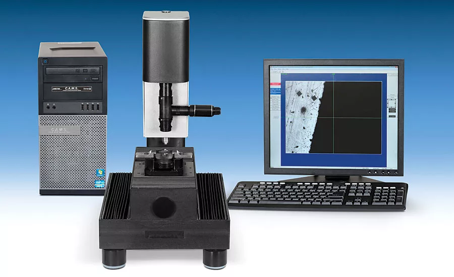
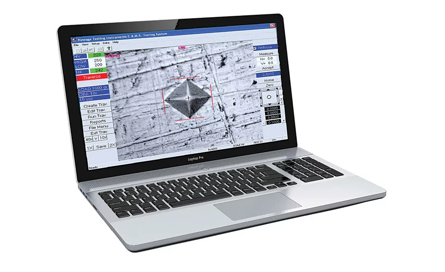
Where the need for more frequent or higher volume testing is required, some level of computer assistance is a benefit. Most microhardness testers, regardless of age, can be adapted to a computer assisted measuring system (C.A.M.S.) that allows on-screen, automatic measuring and analysis through a camera and software installation directly on a PC or laptop.
With today’s technology, impressions can be read in a much more repeatable manner by computers, and in a fraction of the time! Another benefit is that computers do not get bored, or tired. They have a greater sensitivity for shifts in contrast and an ability to repeat their measurements.
The alternatives to traditional optical microhardness testers are direct-reading, depth- of- penetration testers that utilize the direct reading, depth of penetration based on the Rockwell principle of testing with microhardness appropriate loads. As these devices are measuring depth, they are not influenced by the operator and can read on far rougher surfaces. Test cycle times also are reduced dramatically. In other words, these microhardness testing alternatives can reduce the risk of operator error even further.
MICROHARDNESS TESTING ALTERNATIVES
Direct-reading, depth-of-penetration testers that use the Rockwell principle and yet work in the load range of microhardness testing have been available in the marketplace for a number of years.
So why and under what conditions can a direct-reading microhardness tester be used as an alternative to regular hardness testers? Let’s first look at the why.
First, direct-reading, depth-of-penetration testers are much faster than traditional hardness testers. Instead of a single reading taking 30 seconds or more, a measurement with these testers can be made in as little as six seconds. With the alternative microhardness tester the measuring is done during the test, not as a separate function, as it is normally done with a traditional hardness tester. When doing a series of tests to measure case depth or heat affected zones on welds that decreased time for each measurement can turn a 30-minute project into a two- or three-minute project.
A second advantage is the complete removal of operator influence over the test result. There is no judgment call to make as to where the edge of the impression is. Also there aren’t different measurements from different operators, even on the same impressions. All an operator needs to do to conduct a test is to locate the test position or, for a series of tests, select a starting point and push the start button.
A third advantage is that sample parts do not need to be polished to a near mirror finish. In many cases, the finish produced by a cutoff saw can be accurately measured using an alternative microhardness tester, or the parts only need to be polished with 600 grit paper. That not only saves additional time but also the substantial costs of prep consumables.
So, when can a direct-reading, depth-of-penetration tester be used, considering that these testers do not have an ASTM standard to follow?
When a manufacturing concern does substantial testing between manufacturing processes, or if a business manufactures a range of products for its own consumption, such as parts used in a larger assembly.
Alternative microhardness testers have found many successful applications across a number of industries. Direct-reading, depth-of-penetration testers have already been widely accepted in many manufacturing industries, including automotive, bearings, gearing, medical and tooling. Q
Looking for a reprint of this article?
From high-res PDFs to custom plaques, order your copy today!


