A deeper look into using machine vision software and tools for applications in vision guided robotics.
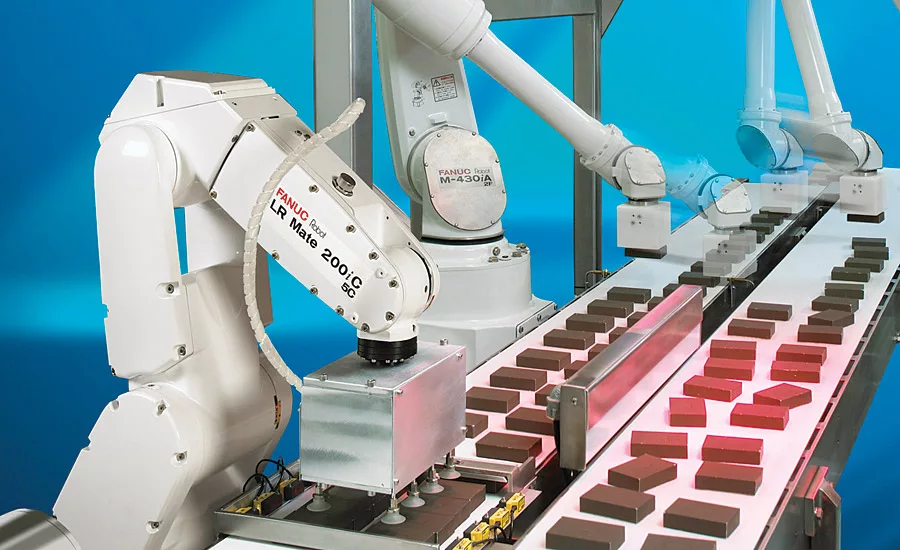
Machine vision for robot guidance continues to enable a wide range of industrial applications like this one performing food product packaging. At the root of the process are a variety of machine vision tools used in the successful programming and execution of this and all VGR tasks. Source: Fanuc
Practical implementation of a successful vision guided robotics (VGR) application requires an understanding of general architecture and design, lighting and imaging, 2D and 3D technologies, robots and calibration. These and other important broad concepts have been discussed in previous articles. In this tutorial, we dig deeper into programming and execution to examine some basic machine vision tools for 2D VGR, and how to apply them for successful applications. This important topic is not just for engineers and programmers. Anyone involved with the design, management, and execution of VGR applications will benefit from a better understanding of these fundamental application techniques.
Certainly it is critical in a VGR application to carefully consider all of the broad system design and specification topics mentioned above. At some point, however, it is all about the software. The competent selection and application of available machine vision tools ultimately defines the capability, reliability, and performance of a VGR system.
The actual techniques for configuring and applying these tools vary widely by product and application. At one extreme, a simple VGR application might be taught with a single, or series of button clicks on a graphic user interface. Highly complex, very unique applications might involve complex low-level programming. Outside of these extremes however, there are many machine vision products intended for general purpose guidance that typically allow the VGR engineer to easily select, configure, and apply suitable machine vision tools for a specific task. The exact specifics of how to do the tool configuration over the wide range of products is well beyond the scope of this discussion. However, the selection and application of machine vision tools for VGR is mostly a generalized task, and the following tips and techniques hopefully will provide a strong starting point for your successful VGR application. (Please note that the scope of this article is constrained to 2D guidance, although many of the concepts could relate to 3D guidance applications as well.)
Robot Location Basics and VGR
Let’s start with a brief review of “location” as the term applies to robot guidance.
At their most basic functionality, most robots move without actually knowing where they are going. A series of specific positions can be taught in advance (by manually moving the robot and storing each position), and the robot can “play back” those positions in a series of moves. It’s not necessarily important where the points are with respect to any spatial reference.
In practice though, most robots do “know” where each point is, and those points are relative to specific 3D coordinate systems (often called a “frame”). The part of the robot that moves to any spot is a “tool center point” (or “tool frame” or “tool center point frame,” for example, a specific spot on a gripper might be a tool center point). While there always are defaults, it is possible and often necessary that the robot operate in one or more user-defined coordinate systems which are an arbitrary subset of the default coordinate system, each with their own origin and vector angle. The robot program also might use multiple tool frames.
While convenient in basic robot programming, these concepts are critical to VGR applications. A properly calibrated vision system must locate an object and report that position accurately within the coordinate system reference that is expected by the robot (as configured through calibration). Expanding on this concept, some machine vision systems are able to provide either absolute or relative offset positions for a located object.
Absolute Positions
Absolute position (sometimes called “found position”) with machine vision for VGR is intuitive. The vision system locates the object and reports the position in the desired coordinate frame. The robot executes a commanded move and the tool goes directly to the found position. It’s important to understand that the point found by the vision system is defined by the configuration of the vision locator tool. It is up to the vision system to set that point so that it actually is the desired “pick position” on the object. Further, if the position needs to be adjusted, the adjustment must be made in the vision system, not on the robot.
Reference Positions and Relative Position Offsets
It sometimes can be limiting to require the robot to grip a part at exactly the point located by the machine vision system. It can be more flexible in many cases to simply offset a taught reference pick position on the object that is relative to the object absolute found position. This technique allows a robot programmer to use the vision system to locate a part, yet pick the part at a point different from the point trained in the vision system. As such, it becomes very easy to change the pick point as required without changing anything in the machine vision tool. Also, using an offset position for guidance eliminates the need to use a specific tool center point as all picks are moves relative to an arbitrary TCP. (Although having an accurate TCP is good practice and might be needed for other operations.)
Note that this task is not as simple as recording a nominal point and then subtracting the difference in x, y, and rotation (for 2D guidance) from subsequent points. Doing so will produce a usually grossly incorrect point. More complex geometric transformations are required to apply the offset. Fortunately, vision systems with this capability perform these calculations automatically to deliver the relative position offset to the robot.
Machine Vision Location Tools
If you have used machine vision for inspection tasks, but are new to VGR, you will notice that the tools often are the same, but that the concepts driving tool selection and application are sometimes much different. Instead of detecting features/defects, presence/absence, or providing measurements, machine vision for VGR, by definition, must provide a reliable and repeatable location for an object. Certainly those inspection actions might be part of a VGR application, but the primary result will be a position or relative offset.
Certain specific machine vision tools natively provide object location. Others can be combined to deliver a location. Let’s start by looking at a couple of tools that are natural locators.
Pattern Matching
Some have called this algorithm true “artificial intelligence,” and the tool has a variety of different commercial names depending upon the product manufacturer. In general, pattern matching is the process of finding a pre-trained feature or object in an image. Some pattern matching uses an image as the trained feature (often referred to as “normalized correlation”), but the more contemporary and widely used tool uses grayscale changes or “edges” as the data for the search model. Because these training data are point-based rather than image-based, the tool often is referred to generically as a “geometric pattern match.”
In execution, the pattern match compares points in the model with points in the new image. When it finds candidate matches, those candidates are scored based on a percentage of match.
Because it usually uses a lot of gradient data points, a pattern match locate can be repeatable to sub-pixel values (manufacturer estimates often are 1/40th of a pixel or better). Be careful though to always evaluate performance of any machine vision tool using real-world imaging with the part(s) you intend to locate.
For the right type of feature or part, a geometric pattern match can be very easy to implement. However, it is similarly easy to misapply this tool, and unfortunately it can end up being a source of unreliability in VGR implementations. Let’s look at a few tips to ensure a pattern match tool configuration is robust and reliable.
Train the model on repeatable features with unambiguous geometric structure: Always take care in training the target model. The model should only contain features that will be present in all target images. Edges caused by shadows, glare, or things that are not common to the part (like an area of print or a surface scratch) should not be trained or should be removed from the model. The trained features also must comprise an object that has a well-defined geometric structure.
Use rotation, scaling and warping (aspect) parameters carefully: These geometric adjustments allow the tool to match the model when the target object has changed somewhat in the new image. The changes could be due to part positioning or part variation or other reasons. In any case, over-application of these parameters can cause incorrect position reporting, or even the location of “ghost” objects in the image (a “find” reported where no object really exists). However, it remains important to be able to handle actual circumstances that change the observed part geometry and we’ll discuss some of those later.
Ensure that features which determine part location are unique and have enough relative size to overcome normal variation found in the other areas of the model: In actual execution, part and image variation will result in a model match on even the best features to vary by 5-10% or more (if the variation on consistent objects is much more than that usually it can be traced to bad part illumination or other external causes). If a small feature determines part location or orientation, the size, in percentage, of that feature relative to the rest of the model must exceed the normal variation in the model matching. Some tools allow you to emphasize the response of certain areas of a model, and this can help. It might be better to use a secondary locate over a smaller search area on the object to more accurately determine location or orientation in these cases.
Blob Analysis
Other names for this tool are “connectivity” or “particle analysis.” In all cases, the tool operates by “binarizing” the scene into areas of light and dark based on a selected (or possibly automatic) threshold point in the grayscale image. A target “blob” feature can be light on a dark background or dark on a light background. The blob tool can extract a lot of statistical information about each target, and that information can be used to “filter” the response to only the desired features or objects.
One benefit of this tool is that it can be configured to find objects with widely varying shapes. Multiple objects in the same scene should not be touching, although often some image processing (morphology or other spatial filtering) can “separate” parts that might be touching in the image.
Blob processing is highly dependent upon consistent illumination that is repeatable from image-to-image. It is very well suited to back-lit scenes, although with care, standard machine vision front-lighting certainly can be implemented to suit a blob tool.
Other Location Tools
There are few other standard machine vision tools that can provide a unique location without combining them with other processing. For example, some tools perform linear or circular regressions once edge point content has been extracted from the image. Measurement tools like “calipers” which find edge points might return a location of the point or the center of the object. In most cases, these tools must be combined in order to return a unique point for object location. Take for example a linear regression. The tool will return a line in space with a related point, but where exactly is that point when the object changes position? A secondary location must be found by another tool which will geometrically “anchor” the arbitrary point returned by the line.
Lens View Angles and Image Parallax
Most lenses used in machine vision applications for VGR have a viewing angle, which is geometrically dictated by the lens focal length and camera sensor size. (In certain unique lens designs this does not apply, as in telecentric lenses which have no viewing angle.) For guidance, where precise location of an object might be required, this viewing angle can affect machine vision tool performance
The term parallax describes the effect seen in machine vision images where objects are “stretched” towards the perimeter of the field of view because of the different lines of sight produced by the lens viewing angle. The effect is much more noticeable on low focal length lenses (about 16mm and below). For location tools, the result is that the object has a different observed geometry. (A circle becomes more of an oval as the parts move in the field of view closer to the perimeter.) Note that the parallax effect is not an error in the calibration of the system; it is a perception error caused by the distorted part. The locate tool might be configured to successfully handle the image variation, but the underlying concern is than the reported location point on the object as viewed stretched by parallax might not be the same as the point on the real object to be picked.
Parallax can be minimized by using higher focal length lenses at longer standoff distances for a given field of view. In some systems the image can be “warped” based upon calibration to make a mathematical correction before locating the object. For high precision locates it is important to consider parallax and know how it might affect the application.
The lens viewing angle also impacts the perceived location of a part when the part height changes in the field of view. The calibration for 2D VGR in most vision systems is accurate at a specific distance from the camera. With some advanced techniques, the calibration can be adjusted at run time for different distances, but the part distance still must be known in advance. Again, because of the lines of sight based on the image angle, an object that is higher or lower than expected will be reported at an incorrect position with respect to the calibration plane. As with parallax, this effect is more noticeable towards the perimeter of the field of view.
Sometimes parts cannot be presented at the same height, or parts with varying heights will be processed. If an advanced perspective calibration is available, it is usually possible to just specify the part height prior to processing a locator tool or use different tools for different height parts. Sometimes multiple planar calibrations are incorporated. If those options are not feasible, it might be necessary at the extreme to change processing to a 2 ½ D or 3D system that can detect the part height and correctly return the part location.
Additional Processing
Finally, let’s consider the use of additional processing beyond a fundamental location tool. Although unfortunately a common configuration approach in VGR, it is almost never the case that the application of a single, bare, locator tool really results in the most reliable and robust, real-world execution. The addition of other tools for the purpose of checking or refining the location output often greatly enhances a VGR application. Remember, in robotic guidance, the result of an error is not the same as it is in machine vision inspection tasks. With VGR, an incorrect location causes the robot to miss or mis-pick the part and the possible result is a physical crash damaging the part, surrounding equipment, or even the robot. Not at all a desirable outcome.
Once an object is located, additional processing can be done—relative to the location of the located object. This concept is sometimes referred to as the use of “child tools” because the additional tools are used as children of the original locate, and by design are intended to “float” with the location of the parent object. (Sometimes this technique also is referred to as “dynamic windowing.”) Keep in mind that for guidance applications it is very common to be working with multiple target parts within an image. In some systems, the child tool processing can be automatically configured to execute on every instance of multiple objects located by a parent locator tool.
Regardless of the technique, the addition of simple secondary locate tools to ensure precision, or simple tools like a histogram to check for interference can be critical in a VGR application.
In conclusion, while we have not had time to address every aspect of programming and execution for VGR, hopefully these few observations and tips will help to make your next guidance application reliable and successful.
Looking for a reprint of this article?
From high-res PDFs to custom plaques, order your copy today!


