Software & Analysis
Automating Scan-Based Inspection for Repeatable Process Control
Metrology software is at the core of process control because it manages all the measurements and drives productivity.
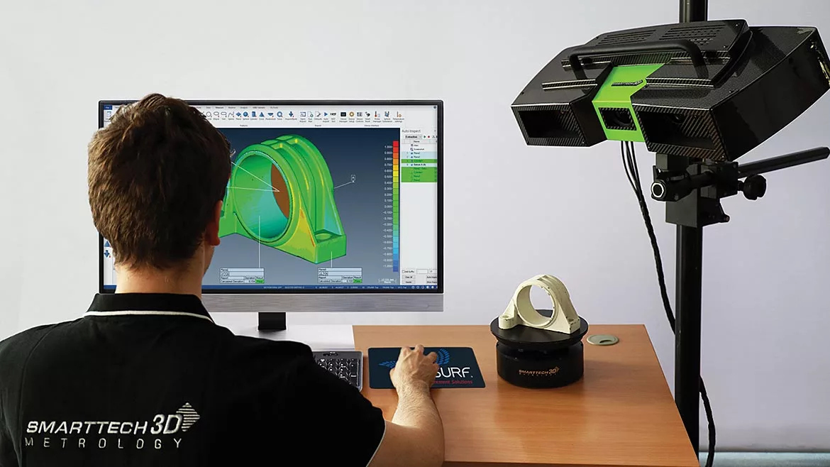
Image Source: Verisurf
Portable coordinate measuring machines (PCMMs) have evolved to be more accurate, more versatile, and exponentially more powerful. Add to the mix today’s process-driven metrology software, and you get improved process control with repeatable results. Portable articulating arms, laser trackers, laser scanners, and other 3D measurement technologies can all benefit from automated scan-based inspection using established and controlled repeatable software inspection plans.
PCMMs automated with the proper inspection software deliver user-prompted, repeatable inspection plans that can be quickly and easily set up and executed using virtually any 3D measurement technology across the manufacturing enterprise. The repeatable, process-driven automation delivers quality plans that build customer confidence with your QA workflow and improves your product approval by source inspectors.
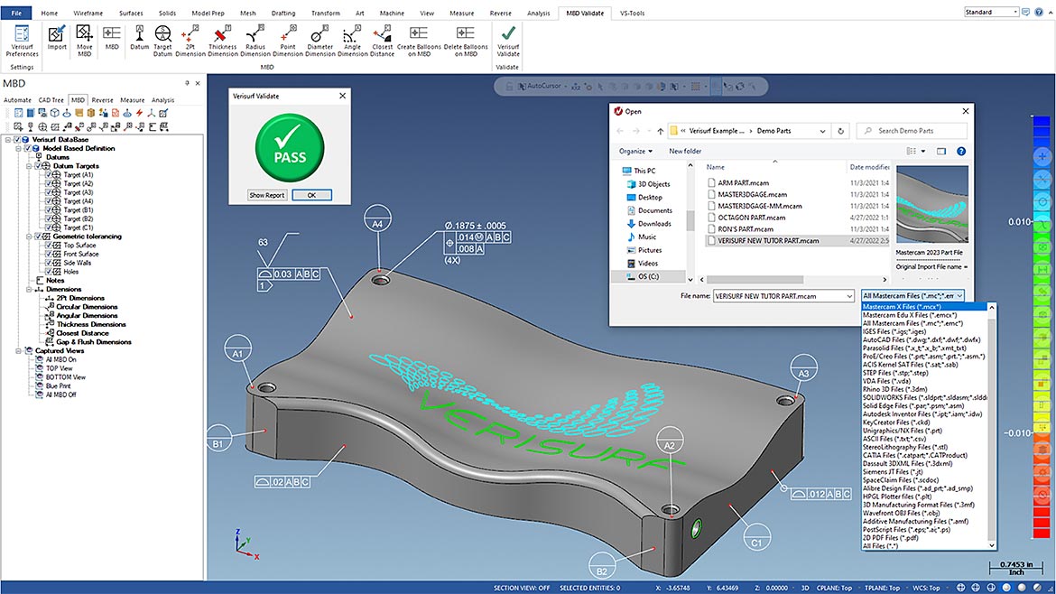
Import CAD Model - Verisurf is committed to Model-Based Definition (MBD) and pulls intelligent GT&T information directly from the native CAD model. If necessary Verisurf VALIDATE will confirm the precise translation of the model. Image Source: Verisurf
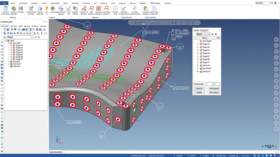
Create a Repeatable Inspection Plan - “MBD to Plan” automatically creates inspection sequences based on datum callouts, datum features, and surface profiles. Feature extraction zones can be refined for accurate results from unique geometries. Collect discrete point grids or slices during or after scanning. Image Source: Verisurf
How do you automate a PCMM? By creating inspection plans that reduce human variability. Implementing repeatable inspection plans increases process control, a core tenet of QC while speeding up the process, lowering costs, and helping to end bottlenecks. For example, a programmer or similarly trained metrologist can create the inspection plan offline while a technician, inspector, or even a new hire can execute the plan quickly and produce repeatable results on-demand. The inspection plan controls the process to prevent user errors, ensures characteristic accountability, and automatically calculates the tolerance condition, including GD&T and reporting. The operator is alerted of any out-of-tolerance conditions by audible sounds and visually notified with pass/fail color indicators. Measurements are automatically formatted to an inspection report for QC and synchronized with enterprise databases for collaboration and statistical analysis. The complete process is controlled from beginning to end and executed the same way every time.
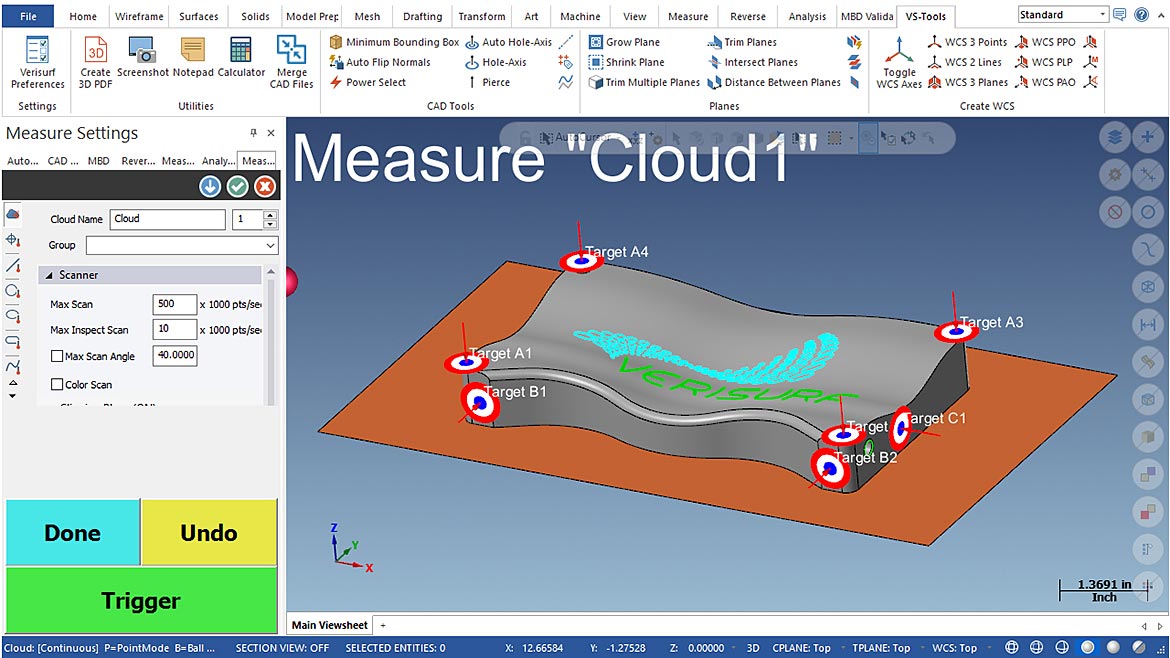
Pre-scan Align & Optimize Setup - Simple yet powerful, datum or best-fit alignments can be applied before or after scanning. Setting the Clipping Plane eliminates unwanted “overspray.” A variety of filters can be applied before or after scanning as well. Image Source: Verisurf
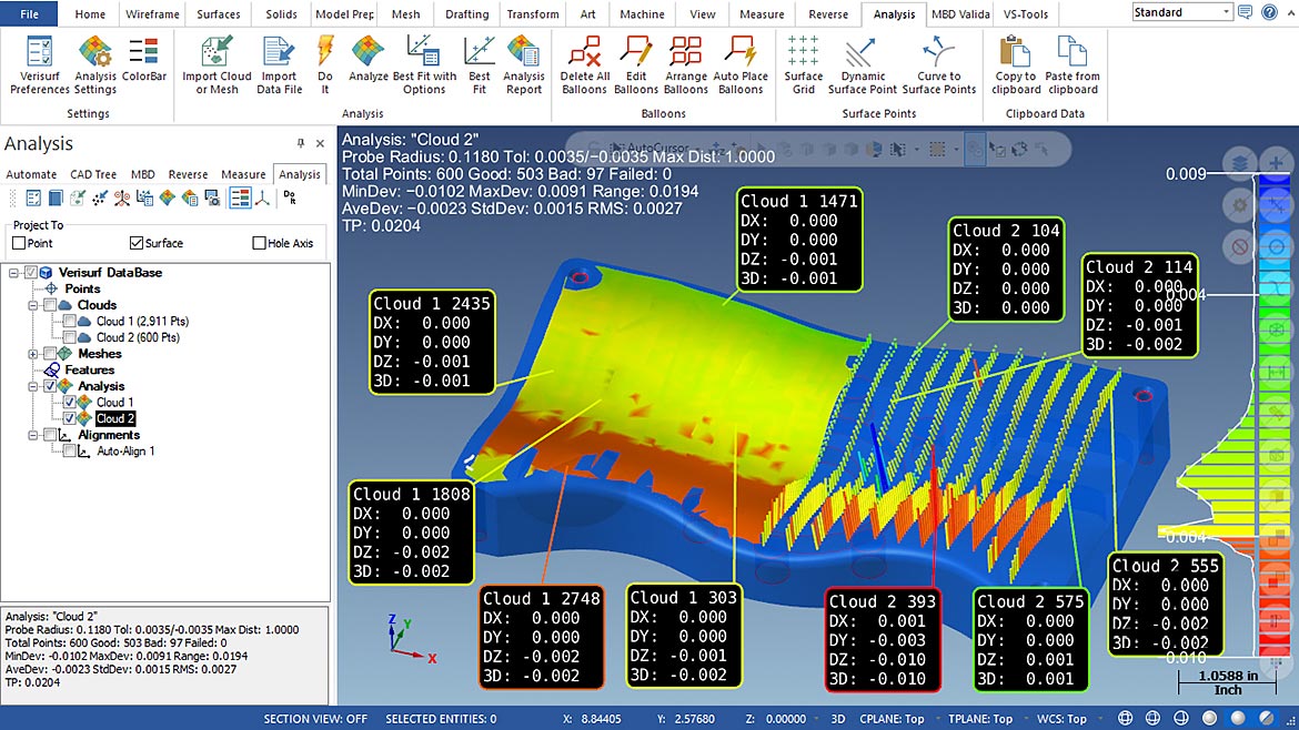
Analysis To CAD - Basic analysis of inspection data to CAD is automatic or one mouse click. There are controls for viewing your data in endless ways to improve the clarity of your part condition. You get many options to test scenarios with the data to help understand and correct your manufacturing process as needed. Image Source: Verisurf
Many PCMMs today are multi-sensor devices, allowing users to choose between contact probing, continuous contact scanning, and noncontact scanning. Multi-sensor devices provide flexibility to select the type and amount of data to be captured, depending on the part and tolerances. One thing all 3D measurement technologies have in common is that they collect data, but that is where the similarity ends. Probing technology will typically collect hundreds of measurement points during a typical part inspection while scanning technology will capture millions of points. 3D noncontact scanning is one of the greatest advancements in measurement technology today. Just think about how the camera in your smartphone has changed over the last few years. Scanners are becoming much more powerful with higher resolution capabilities and enhanced capture speeds. High-end portable scanners can capture over two million measurement points every second. It is essential that your inspection and measurement software can match this performance; otherwise, you will find yourself waiting when processing the data and analyzing tolerance conditions.
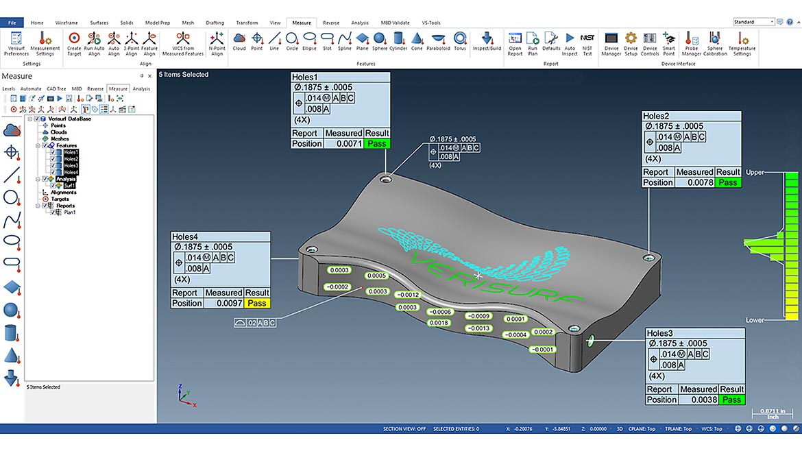
Graphical Inspection Results with Feature Control Frames - Apply GD&T before or after the inspection, and display feature control frames from the model or create them directly connected to the features they control. Setup the view you like best for presentation and it will be automatically saved for subsequent part inspections. Image Source: Verisurf
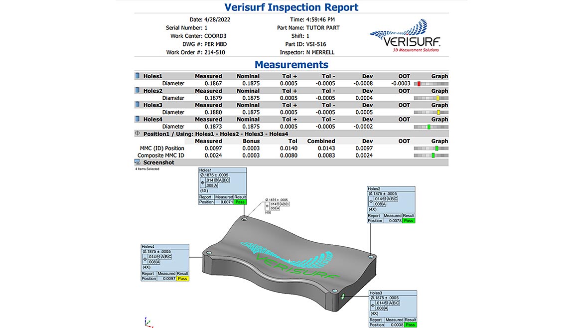
Reporting - Inspection reports, including AS9102 First Article Inspection, and PPAP can be output in a variety of formats: 3D PDF, Excel, PowerPoint, Word, HTML, text, or output to a database. Present clear results of your inspection to communicate in detail or summarized to suit your needs. Image Source: Verisurf
There are many excellent PCMMs available to choose from, depending on your unique measurement requirements. The key is to standardize your shop on software that automates them all and allows you to quickly switch between them
- You want to invest in a measurement software platform that can drive all your measurement devices, regardless of brand
- Your inspection and measurement software should have a complete CAD engine and support intelligent Model-Based Definition (MBD), where the CAD model can be used as the design, manufacturing, and inspection authority. MBD enables the intelligent application of GD&T, helps simplify and automate inspection planning, and is a crucial element of maintaining process control
- Your inspection and measurement software should import all popular CAD file formats and validate the model geometry
- Your inspection and measurement software should be compatible with and connect to on-premises or cloud-based inspection data management and statistical process control (SPC) software

Master3DGage is an example of a multi-sensor device that allows the user to choose between contact probing, continuous contact scanning, and non-contact scanning. Multi-sensor devices provide flexibility to select the type and amount of data to be captured, depending on the part and tolerances. Image Source: Verisurf
Metrology software is at the core of process control because it manages all the measurements and drives productivity. Measurement software that supports scan data is continually evolving to keep up with technology and reduce time-consuming manual processes. Scan datasets can be exceptionally large, and there is a tendency to over-scan, collecting redundant data. Add to this alignment, analysis, and reporting challenges and you will appreciate the power of today’s latest software.
Using software automation to program inspection routines and guide PCMMs makes the whole inspection process faster and easier than ever before. Inspection and measurement software that is based on intelligent CAD is important as it always maintains constant associativity with the nominal CAD model, including edits or additions to GD&T callouts. Users, working in an interactive 3D CAD environment, especially one that is Windows-based, with intuitive point-and-click, drag-and-drop, and object-oriented programming, will become proficient more quickly.

Verisurf 3D Scanning and Reverse Engineering software was used in conjunction with a handheld peel 3D scanner to reverse engineer the fender and flare on this highly customized Ford Bronco, producing an intelligent 3D CAD model. The CAD model was then used as the design authority for production and quality verification using Verisurf model-based, Inspection and Analysis software. Image Source: Verisurf
Automating the process of capturing scanned measurement data and verifying it to a nominal CAD model, then generating a report is easy and repeatable. The first step requires the development of an inspection plan. Once completed the plan can be used for a single part or across a batch of parts. If no CAD model is available, a scan-based inspection plan can still be developed if the metrology software can reverse engineer a known good part into an inspection nominal. Productivity tools and features built into scanning and inspection software have reduced programming time tenfold from just a few years ago.
Looking for a reprint of this article?
From high-res PDFs to custom plaques, order your copy today!


