
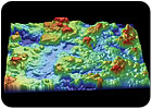
Optical
profilometer data shows false color quantitative height (roughness) images of a
syringe. Source: Veeco Instruments Inc.
Quantitative measurement of surface topography is now a key QC/QA requirement in an increasingly broad range of industries, products and materials. This includes measurements on finished products, research and development (R&D) into new surfaces and surface treatments and in-process monitoring during volume production. Materials include metals, composites, plastics, paper, painted and plated surfaces, porous surfaces and glass. Drivers for these measurements range from critical functional and performance impact, as in the case of a partially processed semiconductor wafer surface, to expected lifetime, such as for hip implant bearing surfaces, to aesthetic considerations, an example being orange peel in automotive paint.
A number of different contact and noncontact techniques currently support this application diversity, the two most widely used being white light interferometry and stylus profilometry. Now another technique with even higher resolution-atomic force microscopy- is poised to transition from the lab to at-line and on-line applications.

Optical profilers are well-suited for measuring surface roughness on razor blades andother blade types. Source: Veeco Instruments Inc.
White Light Interferometry
White light interferometry, often referred to as optical profilometry, is a versatile and powerful optical method that uses light waves as an extremely precise ruler. This is accomplished using the same interference phenomenon that produces colored bands when sunlight is reflected off a very thin film of gasoline floating on a water puddle.An optical profiler is a type of microscope in which light from a lamp is split into two paths by a partially reflecting mirror called a beam splitter. One path directs light on to the surface under test, the other path directs light to a very flat reference surface. Reflections from the two surfaces are recombined in the microscope and imaged at a digital camera.
When the path difference between the recombined beams is on the order of a few wavelengths of light or less, interference occurs. This produces a series of dark and light bands, called fringes. These fringes correspond to the surface contours of the test surface, mapping its vertical (Z axis) topography at a resolution as high as 0.1 nanometer. The XY resolution depends on the choice of objective and the number of camera pixels, and can be as fine as 500 nanometers. The technique also provides absolute accuracy ±3 nanometers in the Z-axis.
Current commercially available optical profilers range from benchtop R&D systems to instruments offering streamlined functionality for on-line or at-line process monitoring. The most advanced of these generate statistical surface topography data, such as Ra and Rq (Average & RMS roughness), and even include image analysis software that calculates feature widths and relative positions, and which can be customized to identify deviations from an ideal shape. They also enable screening for defects, such as scratches and pits, at operator-specified lateral and vertical thresholds, with automatic part rejection, and cause-logging for improved process control.

White Light Interferometry Applications
The advantages of optical profilometry are versatility, speed and wide Z-axis dynamic range. Plus, this is a completely noncontact method. The large dynamic range of today’s digital cameras allows its use with surface reflectivities ranging from 0.5% up to more than 90%. Moreover, because the optical profiler is an imaging tool that makes area measurements with each data acquisition event, it can profile a surface much faster than a tool that has to proceed serially point by point.
Lastly, the optical profiler offers a very large Z-axis range, from a few nanometers up to feature heights as great as 10,000 microns.

In terms of high profile applications, this technology is now used by one of the leading U.S. manufacturers of kitchen and bathroom faucets and related fittings. The instruments are used to examine the surface of parts before and after chromium plating. Originally used for process development, these measurements were developed into process QC specifications that correlate with perceived cosmetic quality as well as resistance to chromium peeling and pitting.
Optical
profilers are widely used in the manufacturer of medical devices as illustrated
in these measurements of a variety of implant surfaces: (A) hip implant head,
(B) hip implant cup, (C) knee implant (load bearing surface) and (D) dental
implant. Source: Veeco Instruments Inc.
In a very different low volume/high value application, NASA contractors use this type of optical profiler to examine and evaluate the space shuttle windows for micro-pits caused by micro meteorite impacts. Based on the results of these measurements, the expensive sapphire windows are replaced typically after four to five missions.

In a typical optical profiler, a digital camera records
fringes that result from reflections off a test surface and a reference
surface. The system computer converts these fringes into high resolution
topographic information. Source: Veeco Instruments Inc.
Stylus Profilometry
Stylus profilometry has been around for decades, yet it remains the tool of choice in several key applications, in part because of its excellent performance to cost ratio. In a stylus profilometer, a diamond-tipped needle or stylus is drawn across a surface by a precision motion stage. Variations in surface topography cause vertical stylus movement that is sensed by a Linear Variable Differential Transducer (LVDT ). Instrument resolution depends on the stylus tip radius, and can be as fine as 1 nanometer in height.Although it is clearly a surface contact tool, the low stylus application force of instruments typically makes this technique nondestructive. The advantages of stylus profilometry are its ability to rapidly perform long linear scans-up to 200 millimeters-its capacity to quantify relatively large step heights, and its low cost.
It is best used for generating transect data; while area data can be accumulated by raster scanning, this is typically accomplished at higher speed and throughput using optical profilometry.
The market for stylus profilometers is dominated by quality applications involving films and coatings. One current example is quality control of the copper plating on the write element of virtually every hard disk drive made. Another is gaging the shape of the microlens used in DVD or similar optical disc players. A key application in the semiconductor industry is control of film stress, both compressive and tensile. This stress warps the wafer and the stylus is used to rapidly measure its curvature and compute the magnitude of the stress from this data.

A
key application for the stylus profilometer is measuring the curvature of
semiconductor wafers in order to compute the stress resulting from applied
surface films. Source: Veeco Instruments Inc.
Atomic Force Microscopy
The latest tool in the arsenal of solutions for QC metrology is the atomic force microscope (AFM). In an AFM, a hyper-fine tip, such as a single crystal of silicon or diamond, is mounted on a lightweight cantilever arm and brought into contact with a surface. Interatomic forces cause deflection in the relatively soft cantilever. At first these forces are weakly attractive, but they become strongly repulsive as surface contact is made. The tiny cantilever deflections are sensed by bouncing a laser beam off the cantilever and onto a position-sensing photodetector.In a modern commercial AFM, the cantilever, or the sample, is mounted on a three-dimensional precision actuator, usually a piezoelectric tube-like structure. Most commonly this is used to maintain a constant interaction force between the sample and the tip. By raster-scanning the tip relative to the sample, a quantitative topographic surface map can be created based on the piezo voltage needed to maintain constant interaction strength. The in-plane (or XY) resolution of an AFM is mainly limited by the tip radius, and it is often 10 nanometers or sometimes better. The resolution in the vertical (Z) dimension is not directly related to the tip, and may be in the range of 0.05 nanometer (0.5 Å).
The instrument also may be operated in TappingMode. Here the cantilever is made to oscillate rapidly like a tuning fork, lightly tapping on the surface. In this mode of operation, the amplitude and phase of the oscillating cantilever are used to gage surface topography. This mode is widely used because it is ideal for delicate samples-even wet membranes-because it avoids lateral forces between the tip and surface. TappingMode is advantageous for hard samples such as metals, because it permits greater precision of force control.
In addition to simply measuring surface topology, the AFM surface-tip interaction can be adapted to make a host of physical, chemical and electromagnetic measurements. Examples include mapping lateral force on the tip (nanoscale friction) and determining piezoelectric activity levels.

Configuring AFM for QC Applications
Because of its nanoscale resolution, the AFM is usually considered the ultimate surface metrology instrument, by some. It can profile surfaces literally at the single molecule level. And unlike earlier research tools, it can work on a variety of surfaces, with no special preparation required. It can even probe surfaces that are immersed in water and other liquids.
This
example highlights the benefits of phase imaging with a AFM. Topography (top)
and phase image (bottom) of a cryo-microtomed multilayer polyethylene sample.
While topography is dominated by large-scale undulations, phase provides a
clean view of the layered structure. Additional fine structure shows the
presence of small droplets. Source: Veeco Instruments Inc.
A typical commercial research application is at 3M, a major component supplier for disposable diaper products. The adhesive tape on these products should be securely closed by a single hand press to give a secure feeling to the parent changing a child. But this depends on a uniform application of adhesive with no bare spots or unequal adhesion levels.
The company recently acquired an AFM to study the adhesive strip using a technique called phase imaging. This is an extension of TappingMode imaging. By mapping out the phase of the oscillating cantilever, phase imaging goes beyond simple topographical mapping. Specifically, it is sensitive to variations in adhesion and viscoelasticity and can provide information about sample composition and microphase separation.
According to 3M, this technique has revealed interesting features that had not been detected by any other technique. Moreover, 3M believe that these features could be important morphological changes in the formulation.
AFMs also have been successfully used in a number of failure analysis and product improvement applications. For example, a fish canning company needed to analyze why their tuna had a shorter than expected shelf life. The AFM was used to analyze coating deterioration on the inner can surface. This revealed that characteristics in the specific water used by the cannery was deteriorating the polymer protective coating used to protect the tuna from the exposure to bare metal.
Now a new generation of compact ruggedized AFMs is poised to take these same capabilities from the R&D lab into mainstream QC operations. Early applications for these new instruments are for monitoring surface roughness and defects in coated surfaces and fine finishes. Other early adopters are in the area of films and foils such as aluminized polymer film.
In conclusion, QC measurements of surface topography in a variety of applications can be serviced with three basic types of instruments-the optical profiler, the atomic force microscope and the stylus profilometer. However, it is not always clear to the uninitiated which of these approaches is best for a given use. Therefore, choosing the right instrument for a particular application requires partnering with a supplier that understands the capabilities and limitations of each of these technologies. Q
Hector Lara is project manager, nano-bio instruments, and Geoff Anderson is senior project manager, profilers, at Veeco Instruments Inc. (Tucson, AZ). For more information, e-mail [email protected] or [email protected] or visit www.veeco.com.
Tech tips
- White light interferometry is an optical method that uses light waves as an extremely precise ruler.
- In a stylus profilometer, a diamond-tipped needle or stylus is drawn across a surface by a precision motion stage.
- In an atomic force microscope, a hyper-fine tip, such as a single crystal of silicon or diamond, is mounted on a lightweight cantilever arm and brought into contact with a surface. Interatomic forces cause deflection in the relatively soft cantilever.