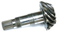
Pinion shafts from the pilot series as evidence of the test equipment and test process suitability. Source: Hommel-Etamic America
As workpieces become more complex and manufacturers are expected to provide fully inspected, documented parts, there is increasing interest in noncontact gaging, specifically optical gaging.
Shafts, often including features such as gears, multiple diameters, notches and grooves, are key, functional parts in a range of products, from aerospace and powertrain to fuel management, bearings, hydraulic and other industrial assemblies. Measurements of shaft features-diameters to surface finish and form-must be accomplished to microns in a single pass with detailed documentation.
To ensure quick, noncontact measurement of shaft geometry, optical shaft measuring systems are increasingly being used in series production situations because of their flexibility in measuring a broad range of part sizes and features.
Optical shaft metrology enables rotational-symmetrical workpieces to be measured quickly and flexibly during the production process. When testing dimensions that are key to overall functionality, in addition to having strict tolerances, accuracy and repetitive precision become primary considerations.
Ensuring Measurement Reliability
When manufacturing shafts for engine, powertrain and transmission components, such as those used in automotive and aerospace industries, it is extremely important to adhere to the strict tolerance limits for diameter dimensions along with the envelope requirements used to ensure assembly functionality.To ensure that the process is well suited to the task, a measurement uncertainty budget should be established to bring clarity and transparency to the situation.
After a target measurement uncertainty for any tolerance of interest is established, it must be adhered to. It is key to using this measuring method to one’s advantage when measuring characteristics that are vital to functionality. By using a measuring uncertainty budget, a manufacturer can ensure that an optical shaft measuring system is suitable for the task in question. This budget can be determined based on regulations as seen in Figures 1 through 4. It is important for both the manufacturer and the end user of any optical measuring system to be aware of both the standard and extended measuring uncertainty of the process.
First, even before the series production begins, the operator must procure a suitable measuring system. This way its suitability for measuring characteristics key to functionality can be ensured, and quality management standards’ requirements can be met and the risk of false test decisions reduced.
The measuring system manufacturer must prove the suitability of the test equipment for the actual measurements to the user. A measuring uncertainty budget offers security for customer commitments and provides notes on minimizing measurement deviations. That is why this process is important to optical gaging.
Two Ways to Suitability
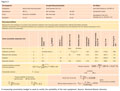
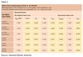
If, for example, the shaft measuring system is used to measure the bearing diameter D of a gear shaft (tolerance field location js7), the standard uncertainty, Udm, of the measuring system is established first from its maximum permissible deviation limits MPE= (2 + D/100) µm, with D in millimeters as seen in Table 1. In a test, the proof was obtained using three hard turned and three ground pinion shafts.Assuming that the rectangular distribution measurement deviations (coefficient b=0.58) of the measuring system are within these “device error limits,” the results for Udm (MPE) shown in Table 1 are obtained.
Key measuring conditions are the monitoring of the calibration state using built-in, fine-tuned standards (calibration disks) as references. It also is essential to be able to automatically correct measurement deviations due to fluctuations in environmental temperature and in the workpieces from the reference temperature of 20 C.
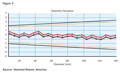
The metrological properties of the measuring system can quickly become clear. The combined standard uncertainty (Udm) of the test equipment, based on the directly active uncertainty characteristics, is determined through repeat measurements on calibrated step standards.
The following are included in the measuring uncertainty budget for the test optical gage for shaft diameter 38.12 js7:
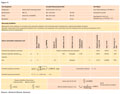
Measuring Uncertainty Budget
The measuring uncertainty budget illustrates that significant parts of the comparatively low combined standard uncertainty of 198 nm for the shaft measuring system used results from the calibration uncertainty of the standard (69%) and the systematic measurement deviation of the measuring system (21%).The comparison of the standard uncertainty of the test equipment with the diameter tolerance indicates that the optical gage is suitable for the measuring task at hand. With comparable measuring conditions, the smallest testable diameter tolerance in the nominal dimension range with this shaft measuring system is 2.978 micrometers.
The high measuring accuracy and the repetitive precision of the measuring system during automated diameter measurements for relatively small tolerance classes also is verified by the other shaft fits that were tested as seen in Table 1.
Based on the fact that the triple standard uncertainty of the test equipment should only equal a maximum of 20% of the measuring tolerance (if T≤IT7), then the smallest testable diameter tolerances Tmin in the nominal dimensions range are the basis for the test plan.
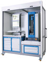
To ensure quick, noncontact measurement of shaft geometry, optical shaft measuring systems are increasingly being used in series production situations because of their flexibility in measuring a broad range of part sizes and features. Source: Hommel-Etamic America
Advanced Measuring Uncertainty
To ensure that correct test decisions are made at the tolerance limits, the advanced measuring uncertainty of the test process must be known. The usual variables that influence the length measurements-operation and temperature-can be almost totally ignored because the measurement is automated and the temperature differences resulting from the measurement deviations are largely compensated for, depending on operating conditions.Workpiece conditions that can cause measuring uncertainty during series measurements, such as the geometric surface structure, form deviations and contamination, can lead to inner part control that equals the standard uncertainty of the object, uObject.
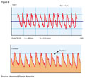
The influence of form deviations and surface roughness when determining the diameter over the cylinder envelope lines also is largely reduced by the choice of the evaluation process. The diameter of the hard-turned bearing seats can, for example, be determined via the peakline of the surface profile and is recorded by the CCD line of the optical gage in high resolution.
The standard uncertainty of the test equipment uPM = 198 nm and the object uObjekt = 473 nm as well as an estimated value of 500 nm for the unknown systematic measuring uncertainty are used to determine the additional measurement program related measuring uncertainty test process U for the shaft diameter 38.12 js7. The measuring uncertainty represents an interval within which the unknown “true” measurement result can be determined with the defined probability (P = 95%, k = 2).
The suitability of the test process can be determined by looking at the ratio of the extended measuring uncertainty to the characteristic tolerance. With a shaft diameter of 38.12 js7, for example, and a diameter tolerance T of 24 µm, the ratio equals U:T = 0.049.
The extended measuring uncertainty of the diameter measurement for the measurement task therefore equals 4.9% of the tolerance. This proves the suitability of the test process for this characteristic.Q
This information is based on work by Dr. Christian Beck, manager of the production metrology and research department at the Institute for Management and Production Metrology of the TEQ GmbH (Chemnitz, Germany), and Dr. Uwe Siefke, application specialist for optical metrology at the Hommel-Etamic GmbH plant (Jena, Germany).