Measurement
Better Measurement Data Reporting to Improve GD&T Effectiveness
ASME Y14.45-2021 Standardizes Measurement Data Content for GD&T Specifications.
When mechanical drawings or CAD models include a note such as “DIMENSIONING AND TOLERANCING PER ASME Y14.5-2018” we should expect to find properly applied, part function-driven GD&T based on the requirements of the ASME Y14.5 standard. Y14.5 defines GD&T methods to define tolerance zones that may be constrained to a datum reference frame, with a requirement that a defined feature element must be inside the tolerance zone for each specification.
When GD&T is applied well, the datum reference frame, tolerance zones, controlled feature elements, and the numerical values that specify the allowable imperfection in the size, form, orientation, and location of part features will directly address the functional requirements of the part. The objective of GD&T specifications is to provide the means to predict whether a part will function or not, based on the measurement data reported for each tolerance specification. A secondary objective is to provide meaningful additional data that helps design and manufacturing teams better understand how their design or their processes are performing.
That value of well applied GD&T can be partially or wholly lost though, if incorrect or incomplete measurement data is reported for those well-developed GD&T specs. Especially when speaking of position and profile tolerances, incomplete or incorrect measurement data reporting too often tends to sabotage the effort and expense put into good GD&T specs. Industry has been operating without standardized measurement data reporting content until recently. ASME Y14.45-2021, titled “Measurement Data Reporting” provides the standardization needed to enable correct part conformance determinations, and the additional data needed by design and manufacturing.
Before we cover what is included in ASME Y14.45, we need to describe what ASME Y14.45 does not provide. Since measurement methods are covered by ASME B89 standards, Y14.45 does not include any measurement method guidance. Y14.45 also does not address measurement uncertainty, or the number of significant digits reported. While Y14.45 includes numbering of tolerances, called “Characteristic IDs”, and example data reports, the specific methods for these elements of data reporting are not mandated.
Y14.45’s focus is on the content of the data, with measured value definitions that follow ASME Y14.5.1’s “Actual value” definitions.
The Y14.45 standard includes three measurement data “Methods”.
- Method A is attribute data, so an “accept” or “reject” outcome only.
- Method B is variable data that directly addresses conformance to the specified tolerance. Examples of method B data are reported values for the unrelated measured mating envelope size, or reported values for position, flatness, parallelism, and a few more. When dealing with a reported position value we will not have information regarding the feature location, and when dealing with a reported profile value we will not have information regarding the feature form or, as applicable, size, orientation, or location. The need for more than method B data, especially for position and profile reporting, leads to the next type of data.
- Method C is any variable data that provides additional information the customer of the data may specify. The specific requirements of method C data are generally specified based on the preference of the data customer. For position or profile tolerances though, method C data includes particular data on a “shall include, unless otherwise specified” basis. We will cover more on this in our data example.
The AS9201B First Article Inspection form was used as the starting point for the report format used in Y14.45, with revisions made to better suit the needs of data to address GD&T specifications. Please review the columns provided in the data report format shown in Figure 1 before continuing.
Figure 1 - The Data Report Format Used for Examples in the Y14.45-2021 Standard
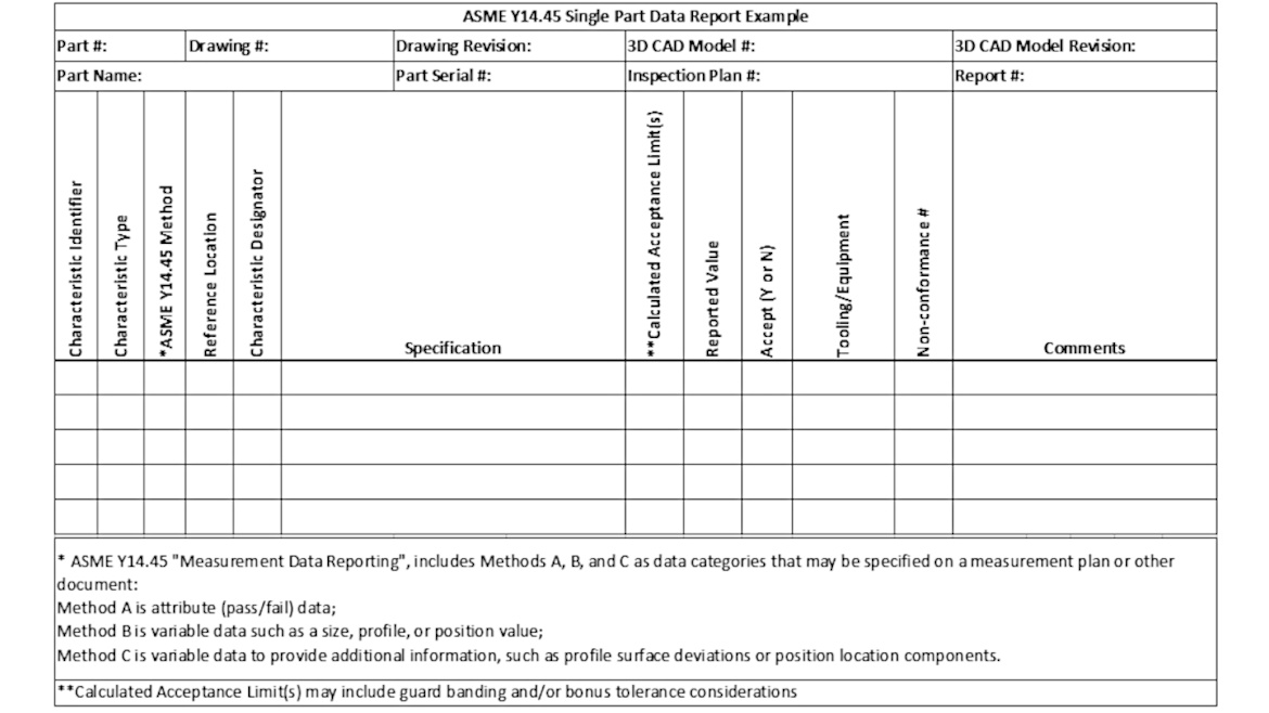
The column titled “Characteristic Type” will hold a three-letter abbreviation or acronym to signify the type of tolerance. ASME Y14.45 provides a full list of those abbreviations, with examples including “MMC” for maximum material condition, “LMC” for least material condition (with both associated with size tolerance data), “FLA” for flatness, “POS” for position, “PRS” for profile of a surface, and “PER” for perpendicularity.
The Characteristic Type information will also appear as part of the “Specification” column information, but the Specification column will have a GD&T font image of the tolerance or a longer string of characters. The Characteristic Type is meant to enable the conditional calculations which will vary based on the type of tolerance being reported.
The column titled “Characteristic Designator” provides the means to identify critical tolerances, sometimes called “Key characteristics”, or other types of tolerances such as “Process Control Tolerances”.
Figure 2 – Example Part Drawing – With Characteristic IDs Included
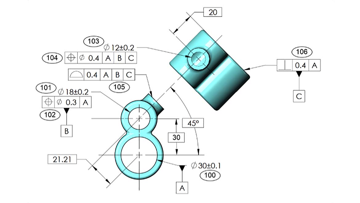
Characteristic IDs, sometimes called “Balloon numbers”, are included on our example drawing. They are best applied directly on the design drawing to ensure the same numbering is used in all geographic locations, but they can be applied later in the product development process, including manual marking on a hardcopy of the drawing by the metrology lab. Y14.45 does not mandate a particular way of applying characteristic IDs. Characteristic IDs are also included in the first column of our example data report, shown in Figure 1.
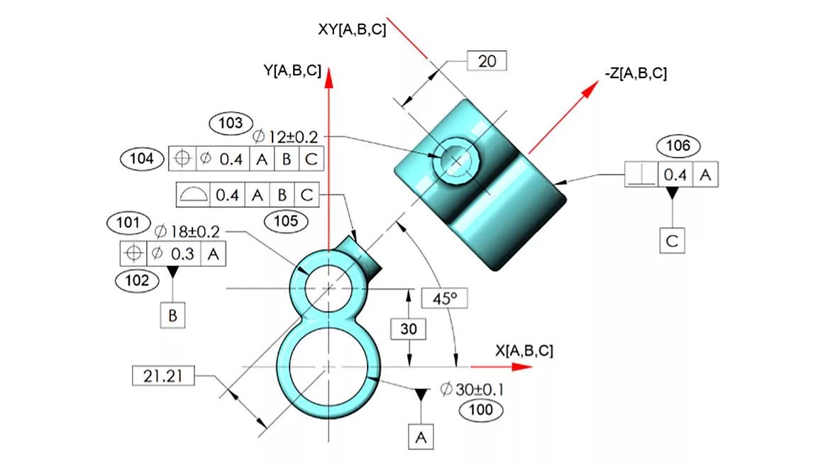
Y14.45 includes specific data content requirements for each type of tolerance specified, with each potential modifier applied, following the requirements in the GD&T standard, ASME Y14.5-2018. We have example data to illustrate some of the requirements and reporting tools provided in Y14.45. Before we review the example data, we need to describe the use of coordinate axes that represent a datum reference frame. They will be used to clarify feature location information when reporting method C data for position tolerances.
In ASME Y14.5-2009, a method called “Customized datum reference frames” was added that requires labeling of the X, Y, and Z coordinate axes of the datum reference frame(s). The Y14.45 standard requires these same X, Y, and Z coordinate axes if “Location components”, as method C data for position tolerances, will be required by the data customer. Location components are one or more X, Y, Z coordinate locations, for one or more locations on the controlled element of the feature. They provide a correct and conceptually valid method of reporting feature location information, to accompany the “Method B” reported position value. Measurement and reporting of basic dimensions may appear to be a way to provide feature location data, but this is prohibited by Y14.45 because basic dimensions are theoretically exact. Basic dimensions do their job of locating and orienting tolerance zones very well, but since they do not vary, they cannot be measured.
Figure 3 – Example Part Drawing with Datum Reference Frame Coordinate Axes Added
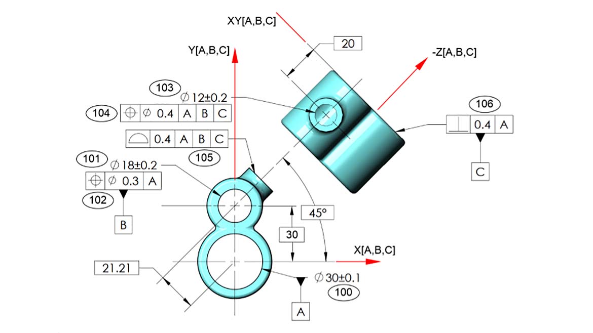
Please note, in the figure above, the “XY[A,B,C]” label is applied to a line with no arrowhead in the auxiliary view. That view is not orthogonal to the front view of the part, so we are seeing projections of the X and Y axes in that view. We cannot label either of these axes, but using an extension of Y14.5 principles, we can label the XY plane of the datum reference frame. We leave the arrowhead off the line that represents the plane because planes do not have positive or negative directions. Please also notice that we included the list of datum features [A,B,C], used to establish our datum reference frame, on each axis label, even though we have only one datum reference frame for this part. This has the advantage of making it clear where these coordinate axes come from, but there is another reason we have done this, which will become clear in our next article about the Y14.45 standard, when we introduce “Reporting coordinate systems”. We will see in that next article, that the data for tolerance #104 on our example part can be reported more clearly with a reporting coordinate system implemented.
Figure 4 – Example #1 Data

As shown in Figure 4, the data for position tolerances includes one or more location components as method C data, to provide feature location information. For the location components, the “.01” and “.02” items are data from two different locations, as described in the “Comments” cells. The data for profile tolerances includes “Surface deviations” as method C data, for at least a sample of the measured points, to provide feature location, orientation, form, and possibly size information. The “.01”, “.02”, etc. items for the surface deviations are for different points that were measured on the feature.
For the perpendicularity tolerance in our example, as with all form and orientation controls, Y14.45 specifies one reported method B value.
For size tolerances, two values are normally required by the Y14.45 standard. One value, as shown in our example above, is likely the diameter or width of the “Unrelated actual mating envelope” of the feature. The other value will then be the local size that addresses the place on the feature with the least material. Size tolerance reporting practices vary depending upon whether the size tolerance is imposing a perfect form boundary at maximum material condition or least material condition, per Y14.5s rule #1, or no perfect form boundary at all if rule #1 does not apply to the particular tolerance.
ASME Y14.45-2021 also includes methods for reporting data for tolerances modified at MMC or LMC, such as position tolerances, with the “Resolved geometry method” (sometimes called the “Axis method”) and the “Surface method” with instructions for calculating variable reported values, rather than just using attribute data outcomes. Also included are methods for reporting data for feature pattern tolerances. These additional provisions in ASME Y14.45-2021 will have to wait for future articles. We would love to hear about any suggestions or questions regarding the Y14.45 standard.
Looking for a reprint of this article?
From high-res PDFs to custom plaques, order your copy today!


