Taking the Edge Out of Noncontact Measurement
It is easy to understand an edge as the transition where a part ends. For a non-flat, prismatic part, that type of edge can be the intersection of two surfaces. Measure those surfaces, and then intersect them in software. That intersection represents the edge whose location can be determined even though it is not measured directly. However, there are other kinds of edges that simply cannot be determined by intersecting surfaces. Source: OGP
Numerous dimensional measurements are made at many places in the manufacturing process. No matter the type of part, from circuit boards to engine parts to plastic connector housings, measurements ensure that parts and processes are in control and of appropriate quality.
The realm of noncontact measuring technologies is extensive. Eddy current and capacitive sensors are just two examples. The category of nondestructive testing (NDT) encompasses many noncontact measurements. Let’s concentrate on two noncontact methods that use optical imaging techniques. Each has strengths at measuring particular features or attributes of parts, and each is available in an automated measurement system.
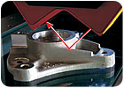
Shown are examples of lasers with different angles of source and reflected light. Source: OGP
Reasons
There are a variety of reasons to use noncontact measurement methods in manufacturing quality and process control. An obvious reason is that there is no physical contact with the part during measurement. This can be important if the part is fragile, deformable or otherwise sensitive to physical contact from a sensor, such as a coordinate measuring machine touch probe. The ability of noncontact methods to magnify details and use light focused to points much smaller than the smallest touch-probe tips makes noncontact measurement the only way to measure highly detailed or micro-scale parts.And noncontact measurement can be fast. Measuring features in a magnified image can be faster than contact probing with the associated approach, contact and back-off requirements for each point. For example, video can capture multiple edge points in milliseconds as part of a multistep measurement routine. A laser can focus on a part, and then scan across its surface returning hundreds or thousands of data points per second. These data rates allow for high-resolution measurements of edge or surface details that are critical for determining proper fit or function of the measured part.

Laser measuring systems can measure a point at a time-three or more points to determine a plane, for example-or they can scan across a surface with the output signal from the sensor being read out at predetermined intervals. Those outputs can be strung together and plotted to represent the contour of the scanned surface. Source: OGP
Because video measurement evolved from optical comparators, many people still think video measurement only works for flat parts. It is true that video measurement of backlighted edges is an important part of manufacturing quality control, but there are many other edges on parts that are used to verify dimensions, locations and alignment.
Non-flat, three-dimensional parts have edges that simply cannot be highlighted from behind, but video can easily measure such parts. Advanced lighting techniques, including coaxial and oblique illuminators, make it possible to highlight even subtle edges for accurate, repeatable measurements.
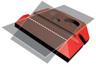
Video measurement is a popular method for measuring edges of parts. Traditionally such edges have been the perimeter and features of flat parts that appeared when they were illuminated from behind, as on an optical comparator. A fixed or variable magnification system enlarges an area of interest. Automatic video measurement precisely identifies the edge boundaries based on analysis of the transition from the brightly illuminated background to the dark shadow. Advancements in edge measurement techniques can determine edge boundaries to fractions of a pixel size of the imaging camera. Source: OGP
Edges
It is easy to understand an edge as the transition where a part ends. For a non-flat, prismatic part, that type of edge can be the intersection of two surfaces. Measure those surfaces, and then intersect them in software. That intersection represents the edge whose location can be determined even though it is not measured directly. However, there are other types of edges that simply cannot be determined by intersecting surfaces.There are edges that are actually co-planar, that is they lie in the same plane. Such an edge can be the boundary between different colors, where two materials are bonded together, or where there is a change in surface texture. Because it is easy for a video measuring system to recognize the boundary where image details change within the field of view of the imaging camera, assigning edge points to that boundary is similar to measuring backlighted edges mentioned earlier. Of course, such surface edges may require the use of directional lighting or light of a particular color to improve the contrast and sharpness of the edge of interest.
There is yet another aspect of edge measurement that some people may overlook. Video measurement of edges does not require that all edges lie in a single plane. Accurate autofocus techniques allow measurement of edges anywhere within the measuring volume of the video system. With appropriate software, relationships among edges can be measured throughout 3-D space.

Source: OGP
Beyond edges
Video measurement is good for more than edges. Video autofocus also makes that technology appropriate for measuring surface points. For example, measure three or more points on a surface and fit them to a plane. Or measure the heights or depths of part features.Lasers bring another capability to noncontact measurement of manufactured parts. Laser light can be focused to a small point. Like video measurement, which uses optics and a camera to capture the image, lasers typically use a separate sensor to determine the location of that focus point. Laser measuring systems can measure a point at a time-three or more points to determine a plane, for example-or they can scan across a surface with the output signal from the sensor being read out at predetermined intervals. Those outputs can be strung together and plotted to represent the contour of the scanned surface.
Other laser scanning techniques project laser light as a line, which either sweeps across the part, or the part moves beneath it. The concept is similar to the scanned point concept except that a full line of data is captured at one time, but is inherently less accurate.
The single-point laser/sensor devices use different designs, optics or sensors to perform surface measurements, each with particular strengths and weaknesses relative to particular part attributes and relative to one another. For example, the reflectivity of the measured part can influence the type of sensor used. A diffuse, matte finish will scatter laser light in many directions while a polished, specular surface will reflect the majority of light in one direction. Optical designs and sensors can be configured for optimal performance from each surface type, or designs can be adapted to accommodate a range of surface types.

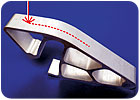
Edges measured with video do not need to lie in the same plane. Source: OGP
Lasers are better at measuring surface contours and step heights than they are at measuring edges. A laser can be scanned across an edge, and the change in signal amplitude from the edge transition can be noted as a single edge location point. However, scanning across an edge along its length to determine its contour would be a time-consuming process.
Combining video and laser sensor technologies in one measurement system can be effective: all measurements are noncontact, the video measures edges and the laser measures surface contours. A well-integrated system is capable of scanning the laser throughout the system’s range of travel in every direction. The part can be set up once, and if the system is CNC-controlled, all measurements can be automatic with no operator intervention. Metrology software handles all measurement data from the sensors equally.
Noncontact measurements offer a number of advantages. They are fast, they minimize the risk of part damage during measurement and combinations of measurement technologies make it easy to verify numerous dimensions in a single part setup. Q
Quality Online
For more information on noncontact measurement, visit www.qualityonline to read these articles:- “Seven Questions to Selecting a Measurement System”
- “Noncontact Inspection Keeps Pace with Production”
- “Select the Right Video System”
Tech Tips
Looking for a reprint of this article?
From high-res PDFs to custom plaques, order your copy today!


