Measurement
Ensuring Precision: A Guide to Calibration in Surface Finish Measurement
The calibration process for surface finish units is simple but essential to the manufacturing process.

All Images Source: Mahr
Surface finish is all around us. It can be a critical aspect of the proper functionality of a workpiece being measured. Therefore, it is necessary to properly calibrate the probing system used to allow an accurate pass or fail of workpieces.
Types of Surface Finish Gages
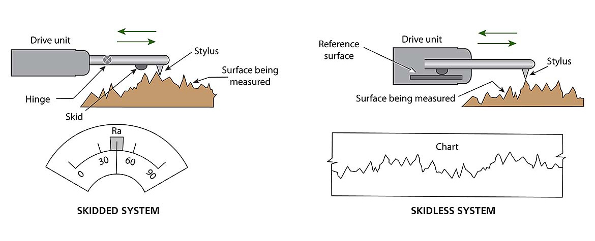
There are two main types of surface finish gages: skidded and skidless.
Skidded units are typically more common as they are less susceptible to background vibrations. A skidded system has a hinged probe. The probe rides next to a skid to measure the probe deflection. Both the probe and skid make contact with the workpiece. These units also inherently filter out waviness, so only short wavelength variations are recorded.
A skidless unit, as implied in its name, lacks a skid. In its place, the drive unit traverses a flat reference datum to measure the probe deflection. This flat reference datum also allows the user to measure workpiece waviness, which a skidded system cannot do.
Whether you are using a skidded or skidless unit, it is essential to calibrate them using certified reference standards that can be traced to international governing standards (e.g., ISO, DIN, and ASME) to provide an accurate pass/fail of the workpiece. Inaccurate pass/fails can lead to assembly failure and remanufacturing of workpieces, which can be very costly.
Optimizing Measurement Accuracy
The main steps in the calibration process for surface finish probes are checking the stylus integrity and performing the actual calibration.
Checking the stylus integrity
If you suspect the results obtained are inaccurate, performing a stylus integrity check may be a good idea. However, this can prove to be challenging since the stylus radius is very small: usually either 2μm (0.00008”), 5μm (0.0004”), or 10μm (0.0002”). Miniscule damage can be nearly impossible to see with the naked eye, which is why probing systems are used in the first place.
A stylus integrity check examines the stylus under a magnifier or measures a stylus check reference standard. Ensuring the probe has the same stylus radius as the reference standard, denoted on its calibration certificate, is imperative. Larger or smaller radius probes will fall into peaks and valleys differently. Therefore, measurements in the same location may have varying results if measured with a 2μm or a 5μm radius stylus.
Typically, a stylus check reference standard has an approximate roughness average, or Ra, of 0.4μm (16μin) and is a sawtooth (triangular) profile. This triangular profile helps determine if there is any damage to the probe, as the saw teeth are so compact that there is little margin for error in the geometry of the stylus. Visually, the saw teeth should be sharp on the top of the peaks; if they are rounded, this indicates stylus wear.
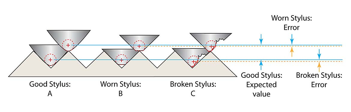
Any error in the geometry of the stylus can and will affect measurement results. This error in geometry is either in the form of wear or damage. Since the diamond stylus is constantly being dragged across a surface with a force anywhere between 100mg and 1500mg (1mN to 15mN), it’s inevitable that the stylus will eventually wear. However, since it is constructed of diamond and the measuring force is relatively low, this usually will only occur after a significant number of measurements and is dependent on the material of the workpieces being measured.
Harder surfaces can make the diamond wear faster. A worn stylus will usually under-report the peak-to-valley distances. Damage occurs when the stylus is dropped, impacted, or has had some sort of heavy physical contact. A damaged stylus can either under- or over-report depending on how (and where) the stylus is broken. A broken stylus can even damage the workpiece being measured.
True calibration
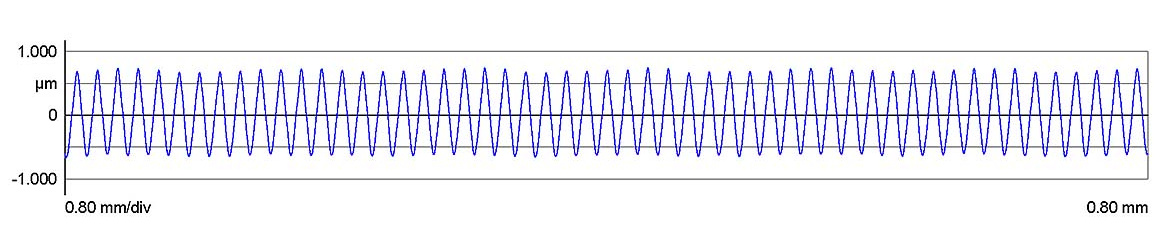
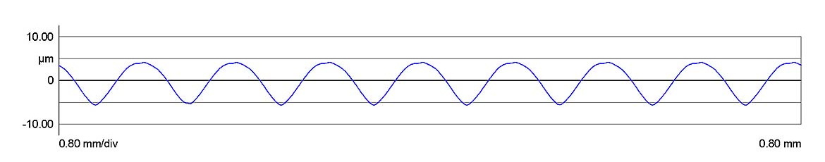
There is also a calibration standard outside of a stylus check reference standard. This standard typically has an approximate Ra of 2-3μm (79-116μin) in a sinusoid wave. Users are often under the impression that the probe must calibrate to an Ra value close to what is being measured. This is actually not true. Large linearity errors can be introduced if the anticipated result requires a much larger probe deflection than previously calibrated. Therefore, if you calibrate to an Ra of 3μm and measure a 0.4μm workpiece, the measured probe deflection is within the calibrated probe deflection, whereas the inverse is not true. This allows the probe to be calibrated over as large a range as possible to ensure proper operation anywhere within that range. Because this sinusoidal wave is not as compact as the sawtooth profile, it is generally not a good indication of probe integrity.
The actual calibration process is simple: measure the calibration reference standard, evaluate with Ra, and see what the result is. A reference standard‘s calibration certificate will indicate the certified Ra value. After the measurements, compare the measured Ra value to the certified Ra value. This should be within an error percentage specified by the original manufacturer (typically no more than +10%). The system should then be adjusted based on the manufacturer’s process.
If the error percentage is outside the allowable range, there may be an issue with the system or probe. It would be a good time to visually inspect the probe or measure the stylus integrity reference standard. Stylus replacement is the only option if wear or damage is found.
If there are no physical indicators, try a different probe. If a different probe produces the same inaccuracy in measurements, there may be damage to the reference standard itself. Reference standards should be recertified every one to two years to ensure accurate probe calibrations. The entire system may need preventative maintenance and calibration from the manufacturer. Since skidless units rely on a flat reference datum for data acquisition, if the datum is no longer flat, it may also need calibration—just like the probe does. This is the straightness of the drive unit, and every drive unit type has a differing straightness tolerance.
After the correction has been applied, it is good practice to verify the unit’s performance by performing a stylus integrity check, even if it was checked before calibration. This allows the user to verify that the unit produces correct results after calibration. In addition, if the result of the stylus integrity check is incorrect, the issue is probably not the calibration but the onset of stylus wear.
When a new probe is received, it’s a good idea to immediately calibrate it in an unworn condition. This allows the user to have a reference for future stylus inspections. As the probe starts to wear, you can see the typical trend of wear or how far away the new correction factor is from the original correction factor.
These steps will ultimately provide a documented method that allows parts to be measured confidently.
Additional Considerations
Reference standards come in all shapes and sizes. As mentioned above, not all standards are appropriate for calibration, but they are an excellent tool for checking if a probe measures a certain range properly. If you calibrate to a 3μm reference standard but really just want to make sure you are measuring an Ra of 1μm correctly, you can get a standard certified to an Ra of 1μm. This is another way to ensure the unit is working as intended. There are also different types of geometries that allow for certified parameter values other than the typical Ra and Rz, such as Rpk, Rvk, or Rsm.
Skidless units can also measure microcontours. If you want to measure step height instead of typical R parameters, depth standards also exist. This is a great way to verify that a singular distance measurement is being measured correctly.
Summary
The calibration process for surface finish units is simple but essential to the manufacturing process. Having a certified reference standard means you can monitor and check performance to ensure the necessary requirements are met.
Looking for a reprint of this article?
From high-res PDFs to custom plaques, order your copy today!


