Custom Surface Finish Gages for Hard to Reach Places
When standard devices can’t provide expected results, a better solution is to custom design a gage to suit the specific application.
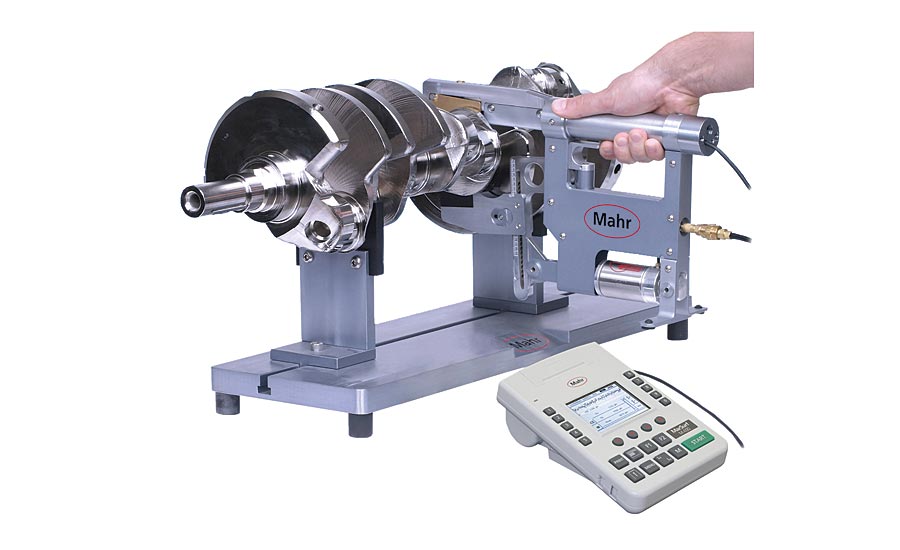
This dedicated blind hole gage positions the drive unit and measurement probe directly over the surface to be measured without the need for long measurement extensions. The drive unit itself is small in diameter and it can be placed within the bore directly over the measurement location.
Beginning some 30 years ago, portable surface finish gages—some small enough to fit in a shirt pocket—brought a new level of part control to the manufacturing floor. Bringing surface finish inspection out of the lab and onto the floor was important for a couple of reasons. For the previous 50 years, part dimensional tolerances had been shrinking. As a result, surface finish and form irregularities were eating up an ever-increasing portion of overall dimensional tolerance, a trend that continues today. It had also become clear that surface finish played a very important role in the performance of the part. The unique characteristics of a surface could determine whether paint stayed in place, lubrication held or leaked, or how much “noise” was produced when surfaces moved against each other.
With proper locating and fixturing, small portable surface finish gages can measure surface finish parameters easily, usually with the touch of a single button. Like dimensional hand tools, general-purpose portable surface finish gages provide easy-to-use and reliable results for many applications. Simply place the pocket-sized gage on the part so that its built-in rest pads locate it in place, press a button, and your results pop up, ready to be compared to the requirements.
But it’s not always that easy. Surface finish parameters can be applied to virtually any surface on a part, from inside a small bore, on a short land, or around a hole, to an OD between two walls, or even on those walls. Oftentimes, a standard portable surface finish gage simply will not work—either the drive unit is too large, the probe arm is too short, or obstructions on the part itself interfere with gage placement.
Probe Arm Extensions
One possible solution is the use of probe arm extensions, though these too have their limits. Adding extensions increases the weight of the probe arm. With skidded probes, extra weight can cause marring of part surfaces, especially with softer materials like aluminum. Plus, additional weight can override the spring force of the skid when the gage is used in positions other than horizontal. This can cause the probe to lose contact with the surface during measurement, causing erroneous measurement results and “out of measurement range” errors. With skidless probes, extra probe arm weight can cause vibration, which also affects measurement results.
In general, probe extensions should be no longer than 100 mm so that skid force does not exceed 0.6 N. Also, the angular range of the instrument should be kept within a 135° envelope, starting at 45° from the horizontal to a position in which the drive unit assembly is facing downwards towards the earth.
Engineered Solutions
When standard devices can’t provide expected results, a better solution is to custom design, or engineer a gage to suit the specific application. This is especially true in cases where there is a high volume of parts and a requirement for fast reliable measurements—often by machinists semi-skilled in dimensional and surface finish measurement—to ensure part quality and eliminate the high cost of part recalls. Dedicated or custom engineered gages are faster, easier to use, and produce results with better performance and GR&Rs. With a dedicated gage, virtually any operator can easily inspect machined parts and make decisions as to their quality. They can even collect the results for process analysis and control.
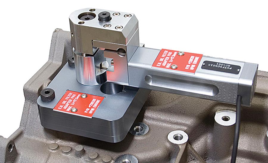
This dedicated gage performs skidless surface finish measurements on the shop floor while keeping the skidless drive unit and measurement probe close together and with no probe extensions. The system utilizes a template fixture for positioning of the skidless drive unit and is slightly elevated to clear any obstructions.
To achieve reliable and repeatable results, any surface finish gage has to do two things: 1) it has to accurately position the diamond stylus at the end of the probe arm to measure the surface area specified, and 2) it has to protect the sensitive probe arm and stylus from damage during the measurement operations. Meeting these requirements for hard to reach surface areas has resulted in the creation of a whole family of dedicated gages, designed to put fast reliable surface finish analysis in the hands of machinists at the point of manufacture—often while the part is still fixtured in the machine tool.
Cylinder Bores
Cylinder bores need specific finishes to balance oil retention and smooth axial movement. They were among the first applications to have dedicated gaging designed for measuring surface finish. Bores come in various sizes and can be relatively deep, some up to eight inches. Prints may call out specific depths and locations for checks, and with up to 12 cylinders in some blocks and four in a vast majority of high volume applications, there are a lot of bores to measure. Thus, gages need to be highly portable and easy for the operator to align and set to depth. The design also has to protect the sensitive probe so it does not get damaged when bringing the gage to the part.
Cylinder bores were probably the first feature to have dedicated gaging designed for measuring surface finish. Characteristics include bores of various sizes, which can be relatively deep, some up to eight inches.
The dedicated portable surface finish bore gage is much like an expandable tri-bore gage. The tri-bore has a certain amount of size adjustment, but can be set to a specific size. This allows it to “lock” in place and helps provide very repeatable readings with no operator influence. The indicating device is also protected by a transfer mechanism so there are no locating forces applied to it when the gage is placed onto the part.
The surface finish cylinder bore gage borrows the same principles. To give it adjustability to lock into various sizes, interchangeable plates are used to achieve the right measuring range for the diameter. Setting the gage with the right set of blocks allows easy entry into the cylinder bore, and once in place, a manually controlled air cylinder expands the sizing blocks so they lock the gage into position.
But the gage’s cylinder has another even more critical function. When compressed with no air applied, it holds the sensitive surface finish probe in a retracted position. This means that during insertion the probe is protected inside the body of the gage. Once the operator is satisfied with the gage location, he applies the air, locks the gage into position and the probe extends so he can make the surface test. When done, the air is released, the probe retracts, and the gage becomes free, allowing easy removal by the user.
Small Obstructed Bores
Surface finish measurements on cylinder head valve guides are especially tough to perform due to their small size (six millimeters) and location within the cylinder head. The most reliable measurements are performed from the “spring side” of the cylinder head as these are most accessible. However, the camshaft towers present a problem since they protrude into the area where the gage drive system must be located for measurement. Having a small drive system is the best technical solution since the drive system can be placed in between the camshaft towers. It is possible to use an engineered gage that eliminates these issues, since the drive unit can be placed close to the measurement location without the need for excessive measurement probe extensions and setup. The operator simply mounts the gage onto the OD of the valve guide and the unit fits within the area to be measured.
Air operated, the journal surface finish gage allows for setting the locking jaws to the approximate size. With manual air actuation, the gage locks itself into position and releases the probe to contact the part. As with all these gages, the probe does not make contact unless the gage is fully locked into place.
Like the cylinder gage, this surface finish version retracts the probe until a mechanical transfer mechanism releases the probe when the plug is in its final measuring position.
Deep Blind Holes
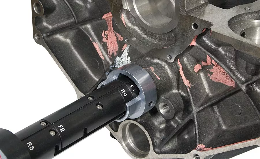
Bores are typically easy to perform surface finish measurements on in a shop floor environment. That is, of course, if the bore is accessible and the measurement depth is kept to a minimum. Engine block camshaft and crankshaft bores, however, are often deep blind holes (up to 500 mm for most engines), and are so small in diameter that a typical surface finish drive unit will not fit inside for proper location for measurement.
Just as important as the bearing and crank journals are the thrust faces they ride against. Another snap gage concept is used to position the surface finish probe here, and with the same thoughts in mind: easy to use, no operator influence, and protected probe positioning.
Typically the surface finish drive unit must be kept external to the bore and a long measurement probe extension used to reach the middle cam and crankshaft bores. However, the ideal solution for performing such measurements is to bring the measurement drive system directly to the surface to be measured.
A dedicated gage can position the drive unit and measurement probe directly over the surface to be measured without the need for long measurement extensions. The drive unit itself is small in diameter and it can be placed within the bore directly over the measurement location.
Obstructed Surfaces
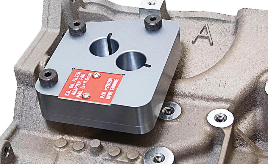
Flat surfaces are also easy to measure for surface finish and waviness on the shop floor as long as the surface is large enough for the placement of the measurement device and there are no obstructions blocking its direction of measurement. Often, however, obstructions and minimal land area prohibit the use of traditional portable devices.
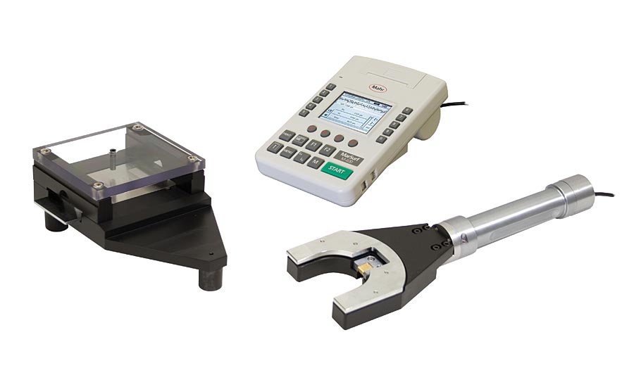
Some surfaces not only have a small land area but also have some obstructions on the casting that prohibit the use of a traditional surface finish waviness system. Normally this surface would have to be measured with a drive system that is kept off and away from the part and a long measurement probe extension would have to be used to reach the surface.
A gage can perform skidless surface finish measurements on the shop floor while keeping the skidless drive unit and measurement probe close together and with no probe extensions. The system utilizes a template fixture for positioning the skidless drive unit and is slightly elevated to clear any obstructions.
Journal Surfaces
Surface finish is very critical on a crankshaft. Rotating at thousands of RPMs, and with bearing and crank surfaces and their end faces in metal-to-metal contact, there is tremendous potential for wear. Surface finish helps determine the life of these products.
A concept similar to a snap gage is used when measuring surface finish on crank journals. The surface finish gage has to be adjustable for various sizes, has to lock in place, and protect the probe.
Air operated, a dedicated journal finish gage allows users to set the locking jaws to the approximate size. With manual air actuation, the gage locks itself into position and releases the probe to contact the part. As with all these gages, the probe does not make contact unless the gage is fully locked into place. The key difference with this gage is that it has a traverse probe operation so that the probe moves horizontally along the crown of the part.
Just as important as the bearing and crank journals are the thrust faces they ride against. Another snap gage concept is used to position the surface finish probe here, and with the same thoughts in mind: easy to use, no operator influence, and protected probe positioning.
Looking for a reprint of this article?
From high-res PDFs to custom plaques, order your copy today!


