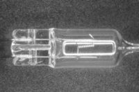
We have all read the Sunday newspaper where we were challenged with finding the difference between one image and an almost identical image positioned right next to it. Sounds easy but some are more difficult than others.
Many machine vision systems are faced with a similar challenge but the stakes are much higher. They must find the difference between one image, a “golden template,” and another image, usually a currently captured image. Any differences might indicate a failed and rejected product. The “golden template,” as it is affectionately known, is considered the standard. It is the perfect image that is defect free. From a manufacturer’s point of view, it is the ideal product. That might be a stretch since there is usually more to a product than what meets the eye, but aesthetics can play an important role in determining the quality of a product. The difference between the golden template and a new image might point out a defect like a missing washer, a missing electronic component or a botched printed page.
Defining the “Golden Template”
As mentioned above, it is the perfect image of the product. Ask anyone who has worked at a manufacturing plant, and they can attest that finding that perfect product might be a challenge in itself. There are always variations from the original design. Some of these variations are subtle and insignificant, but are variations nonetheless. If one were to use the first product off of the production line as the golden template, that first piece might have a variation that would’ve caused it to fail itself. Then using it as the golden template, all subsequent parts without this variation would be considered failures when in fact they might really be good parts.
Another possibility is to sample several parts and develop an averaged image to use as the golden template. The logic behind this tactic is that small, insignificant and subtle variations on each individual part would be diminished in the averaged golden template image. Sometimes this works and sometimes it exacerbates the problem. The golden template may then be a collection of defects which are being used to compare all subsequent images. Maybe this is not a good idea. Still yet another solution is to use a design graphic of the original product as the golden template. Now we have a solution, right? Unfortunately, the production product rarely is identical to the actual designed product. There also are color, scale and reflective properties that sometimes can’t be considered in the design layout. Also the camera perspective becomes an issue because the graphic has no perspective. It is flat and perfect whereas a camera has angular distortion and is oriented to view the product. Comparing a graphic design to a real captured image usually shows many “changes,” even if the product is identical to the graphic of the product.
Generally, most manufacturers recognize the issues associated with defining the golden template and with some compromise, heartache and soul searching, a golden template can usually be defined. Tolerances are eased, important defects are identified and insignificant variations are ignored. So, let’s assume we have a sufficient golden template. How to compare the new part with the template? There are several methods available, but the most common method involves image subtraction. This is where we subtract the new scanned image from the golden template image. In an ideal situation, the resulting image will be black with only lighter areas where changes/differences occur.
Let’s look at the example images on the previous page the image on the left is the golden template and the image on the middle is the newly scanned image. They look similar but when we subtract the two images, we get an unexpected result on the far right. The red pixels are the changes detected.
It appears that there are a great number of “changes.” How could two images that appear to look so similar give such a big difference? Are these changes real? We have to remember that our brains can ignore certain image qualities that a computer struggles to ignore.
What is really going on?
Differences between the Golden Template and the Sample
Rotation: The middle image is slightly rotated by one degree. If we were able to rotate the image back so that they were in the same polar positions, then the results may look a little better.
Scale: When we analyze the two images we discover that the second image is slightly smaller (two pixels) than the first image. This slight scale variation causes the image subtraction to detect it as a change.
Intensity/Lighting variation: The image on the middle is slightly darker than the image on the left and again this slight variation of intensity will show up as change during an image subtraction.
Alignment: The second image is shifted slightly to the right causing the two images to also show up as change when doing image subtraction.
Lens Distortion: All lenses distort; some are worse than others. If the position of a part shifts within the field of view then the distortion on that portion of the lens is going to be different that the distortion experienced in the original golden template image.
All of these factors, plus some others not mentioned, prevent the image subtraction method from effectively giving the user the true changes of the newly scanned sample. If we subtract the golden template from itself, the resultant image should be completely black. Each pixel negates itself because there are no differences, yet our subtracted scanned image is anything but black. Even though our eyes and our brains tell us these images were very similar, our impartial and objective computer told us otherwise.
So how do we get our computer to compensate for all of these factors? There is no one magic algorithm capable of compensating for all of these factors, but we can consider a few. The first is a registration algorithm. This algorithm allows us to align the two images. Imagine the middle image is made of a flexible, transparent material. The material allows us to place the middle image on top of the left golden template image. We can twist it, stretch it and rotate it until the two images lay perfectly superimposed on top of each other. The top image is not completely transparent because it has to have some features to use as a reference to align with the bottom image, otherwise you wouldn’t have any idea where the alignment points are located. These features are the basis for most registration algorithms. Find the features that are common between the two images, then stretch, twist and expand one of the images until all of those features are aligned. The algorithm transforms the images so that they lay aligned on top of one another. Well, not actually, but figuratively, because in the images buffers are aligned in the computer memory.
So we’re done, right? Wrong. Registration only compensates for the alignment of the two images. If the images have light intensity variations, then these will be detected as change. Normally in most machine vision applications, the lighting will be controlled. The elimination of uncontrolled ambient lighting helps minimize the variation of lighting. Nonetheless, lighting will vary over time: lights degrade, power fluctuates, product color may change, camera and electronics temperature may vary, and lenses are non-uniform across the field of view. All of these play a part in light intensity variation. Also light tends to be brighter in the center of the field of view and gets weaker out on the edges. Many cameras come with flat field correction which can compensate for much of the unevenness within the field of view.
In order to remove light variation from the equation we need to balance the intensity of the two images, or we need to use an algorithm that is indifferent to the light variations. Normalizing the intensity is probably the simplest and quickest technique. This is when you study the grey level statistics of the two images and adjust one to better match the second image. In other words, if the middle image is slightly darker than the golden template, then uniformly brighten the middle image so it better matches the intensity values of the golden template. This works when the intensity values are uniformly different but sometimes the lens and lighting cause uneven intensity values.
The best solution for light variations is to use “light invariant” algorithms. These algorithms are based on features of the two images and will work even if the polarities of the two images are reversed.
Now that we have figured out the registration and considered light intensity variations, let’s compare the sets of images on this page to see if we can successfully determine the differences between them.
In conclusion, there is no magic bullet to solve all change detection challenges. However, registration and change detection algorithms can be customized for specific machine vision applications in order to minimize registration errors and to sense significant changes or defects. Once in place, the benefits of a change detection system can add value to the end user by increasing efficiency and consistency. Many of the algorithms can also be accelerated and optimized by utilizing high speed parallel processors like FPGA, ASICS and GPUs, but we’ll save that for a future article. V&S
Ruben Uribe is president of Imaging Technology Solutions LLC. For more information, call (770) 642-0618, email [email protected] or visit www.imagingtechnology.com
TECH TIPS
There is no magic bullet to solve all change detection challenges, but there are tools that can help.
Registration and change detection algorithms can be customized for specific machine vision applications in order to minimize registration errors and to sense significant changes or defects.
The benefits of a change detection system can add value to the end user by increasing efficiency and consistency.


