Optics in Machine Vision
For machine vision systems to take advantage of high-performance sensors, the optics must meet increasingly challenging requirements.
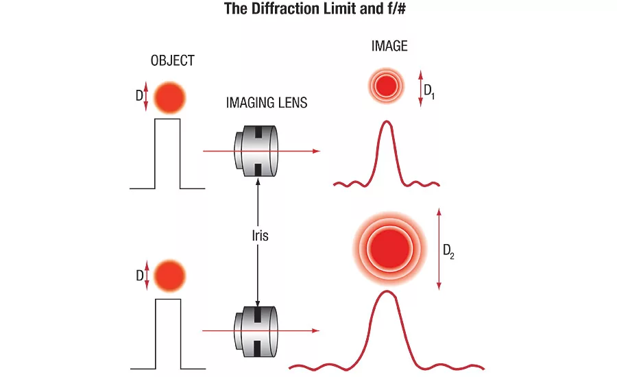
Figure 1. The upper diagram shows the relative spot size created with a lens with its aperture open wide. The bottom portion illustrates how the spot size from the same lens increases as the aperture is decreased. The top image shows the aperture set to a low f/# while the bottom image shows the lens set to a high f/#.
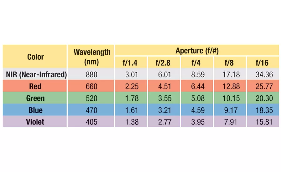
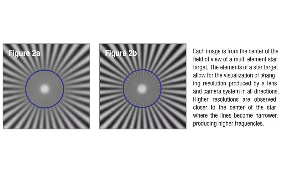
Figure 2. Images of a star target taken with the same lens, at the same f/#, with the same sensor. The wavelength is varied from 660nm (a) to 470nm (b).
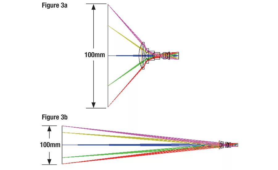
Figure 3: Two lens designs, (a) and (b), with the same field of view and very different working distances.
Both lenses in Figure 3 are imaging the same field of view onto the same sensor, but the lens in a has a working distance of half of its field of view, while the lens in b has a working distance of 3X its field of view. The light passes through the lens in a at extreme angles and the light on the edges of the field of view (magenta/red) have a much longer distance to travel than the light in the center of the field of view (blue). In contrast, the lens in b achieves the same field of view at shallower angles with a smaller path length difference. As a result, the lens in b features a much less complex lens design and provides superior performance at a lower cost.
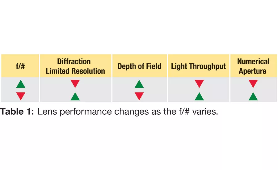
Table 1: Lens performance changes as the f/# varies.
This shows the relative change to a number of key system parameters as f/# is changed.
Over the last decade imaging system designers have faced a new set of challenges. Ten years ago the performance of standard camera lenses was sufficient to get optimum performance out of the available sensors. Sensor resolution is twenty to fifty times better than that available just ten years ago, and pixels in many cases have gotten much smaller, with currently available sensors providing up to ninety times more pixels in a given area. For machine vision systems to take advantage of high-performance sensors, the optics must meet increasingly challenging requirements. Today’s system designers must often coax maximum performance from their optics. But there is no “one size fits all” optical design that guarantees optimum performance, and designers must define their requirements wisely to ensure a given optic will do the job. Before starting to define their system requirements, designers need to recognize that the performance of even a “perfect” design is limited by the laws of physics.
A perfect lens would be one that transferred light from one infinitesimal point from a plane in object space to a unique corresponding infinitesimal point in image space. But no lens focuses light down to an arbitrarily small point. The physical phenomenon of diffraction spreads the light out around the point in image space, typically in a circular pattern called the Airy disk. As points in image space near each other, the disks overlap, until at some point the two spots are indistinguishable. This point, the physical distance representing how close two points can be and still be resolved, is called the diffraction limit. The diffraction limit is controlled by the working f/# of the lens and the wavelength(s) of light that pass through the lens, as in the following equation.
Minimum spot size (object detail) in µm = 2.44 x (µm) x f/#
The laws of physics make the lens incapable of resolving details smaller than the diffraction limit. The most profound effects are seen on sensors containing smaller pixels. While smaller pixels are generally associated with lower cost sensors, that doesn’t necessarily imply a lower cost imaging system. To reach their desired performance in systems with smaller pixel sensors, designers are forced to levy more stringent requirements on the lenses.
For example, consider a lens that produces a diffraction-limited 10 µm spot. In a sensor with 10 µm pixels the spot will spread out over no more than 2x2 pixels. When a sensor with 2.2µm pixels is used with that lens each piece of object detail will be spread over about 5x5 pixels. Even though there are many pixels to work with, the spot is spread over many pixels so the information is somewhat blurry. Usually a lens will have some design and manufacturing imperfections that spread the light out even more, further decreasing the image quality.
The laws of physics offer designers two options to change the theoretical maximum capabilities associated with the diffraction limit equation: first is to change the f/# of the lens and the second is to change the wavelength of light.
CHANGING F/#
Changes in f/# cause several changes in system performance. Generally, changing the f/# is done by adjusting the iris setting of a lens. Figure 1 illustrates the change in relative spot size with a change in f/#. For a lens of a given focal length, a larger aperture represents a smaller f/#. Closing the iris down to a smaller aperture represents an increase in f/#. As shown in the figure, a lens with a smaller f/# produces a smaller Airy disk, indicating that the lens can image smaller details in a scene. But other performance parameters also change with f/#.
As can be seen in Table 1, widening the aperture (iris setting) of the lens will increase the theoretical resolution. But that reduces depth of field—the ability to see object information at different distances away from the lens. Maximizing resolution requires the f/# to decrease, while increasing the depth of field requires the f/# to increase. Essentially, physics dictates it is impossible to have very high resolution over a large depth of field. To optimize both resolution and depth of field, designers need to make compromises or seek more elaborate solutions, such as using multiple imaging systems.
CHANGING THE WAVELENGTH OF THE SYSTEM
The wavelength, or color, selected for illumination can have an enormous impact on system performance. The performance of a high-quality imaging system can be significantly improved simply by switching from broadband to monochromatic illumination. This can be true even for converting from one monochromatic wavelength to a different monochromatic wavelength—say switching from red illumination around 680nm to blue around 480nm. The proper choice of illumination color can make the difference between high contrast and no contrast, and can determine the success or failure of a system.
Lenses typically focus light of different colors at different distances, which tends to make the spot size larger. Reducing the wavelength range as much as possible will enhance any lens’s performance. As seen in the diffraction limit equation, wavelength is one of the variables that affect spot size. Table 2 and Figure 2 each illustrate how spot size (and resolution) changes with wavelength and f/# for a diffraction-limited lens.
REAL WORLD LENSES AND WHAT CAN BE DONE TO MAXIMIZE LENS PERFORMANCE
Optimizing the f/# and wavelength range will not give perfect performance. All lenses are subject to reduction in imaging performance related to the overall quality of their design and fabrication. But designers can get the most out of their imaging systems by implementing some best lens design practices for increasing performance.
Bigger, in many cases, is better. Higher resolution applications benefit from larger optics. Understanding a system’s volume requirements before building is especially critical for systems requiring high resolution and high magnification. Small consumer cameras are impressive, but they do not approach the capabilities required for even intermediate-level industrial imaging systems—partially because of their size limitations. It is often advantageous to specify the vision portion of a system first, as it is typically easier to arrange the electronics and mechanics around the vision portion rather than the other way around.
Don’t get too close. Due to the constraints of physics, attempting to look at fields of view that are too large relative to a lens’s working distance places excessive demands on the design of the optical components and can decrease system performance. It is recommended that a working distance of two to four times the desired field view be used to maximize performance while minimizing cost. Figure 3 shows some of the implications of selecting a working distance outside the recommended length.
There is no universal solution. A single lens that can do everything does not exist. Competing requirements need to be balanced. As resolution requirements increase, it becomes increasingly difficult to decrease aberrations—imperfections that adversely affect performance. For this reason, applications that are superficially similar may require a wide range of lens solutions.
Specify early, not often. Narrowing down the specific parameters required for the imaging system reduces the wide range of available lenses and sensors to a manageable selection of components, increasing the likelihood of success. The more completely a system is specified early, the easier it is to avoid engineering changes.
RELEVANT SOLUTIONS FOR EVOLVING APPLICATIONS
For many years machine vision lens performance exceeded sensor performance. As sensor characteristics improved, overall imaging system performance came to be driven by lens quality. Optics manufacturers have stepped up to the challenge by producing increasingly capable lenses for a wide variety of applications. The important thing now for optical systems designers is to determine their specifications early and work with an optics manufacturer who offers a wide range of lens solutions. If an off-the-shelf lens is not sufficient to meet a system’s performance needs, then designers should be sure to work with a supplier who can understand their needs and efficiently develop custom or semi-custom solutions to meet their goals. V&S
Greg Hollows is the director of the imaging business unit at Edmund Optics. For more information, call (856) 547-3488, email ghollows@edmund
optics.com or visit www.edmundoptics.com.
Looking for a reprint of this article?
From high-res PDFs to custom plaques, order your copy today!


