Integrated Vision
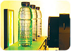
A well-written system spec will help to wade through the wide variety of products on the market, creating a short list of components needed to build the correct system. Source: Edmund Optics
Vision system integration has come a long way. With increased processing power, more powerful algorithms, and lighting and optics designed for more demanding requirements, more applications can be solved today than ever before. Even with all of these advances, however, deploying a complete inline inspection system can be a daunting task. Being armed with the right tools will make the process much easier, and it will yield the desired results in a more cost effective manner in the long run while reducing delays.
Vision is an incredibly powerful tool that can be used to solve a variety of applications. An enormous range of products is available today with an ever-growing base of manufacturers. To add to the complexities, for many applications, products from a variety of manufacturers need to be employed in order to produce the best solution. For example, some optics manufacturers carry upwards of 300 lens options in order to cover the wide breadth of applications and even with this many options they still may not be able to solve every need presented to them.
As a consumer of these products one must come to the table prepared with the right information and questions in order to discern which products and supplier are best suited to meet application needs. This upfront information generally breaks into three areas: specific application requirements, the type of short or long term support required, and of course, the budget. Often the application requirements will drive the type of support needed.
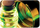
Vision is a powerful tool that can be used to solve a variety of applications. Source: Edmund Optics
Application requirements
Generally these are specifications that are directly related to the parts under inspection, the desired information to be extracted from those parts, and what is to be done to the parts or processes after the results are collected. A system spec or a statement of work can be generated from this information. How comfortable the operator is with the system spec will, in the long run, determine the system’s success. Determining the system spec will drive most of the decision making that needs to be done in terms of products to be integrated.What actually is needed to write a good system spec? First, put together a complete list of everything the system should be able to inspect, the type of data that it should collect and the accuracy of the data that needs to be collected. Next and more importantly, list the reasons for each area of inspection, as well as how important each inspection is relating to the desired outcome.
After this information is assembled, the operator must take what may be the hardest step of the application-break the list into two parts, what the operator wants the system to do and what it needs to do. Of course, everyone wants the system to do as much as possible, but in the long run adding what seems to be small feature sets that are not really required for ultimate system success can lead to greatly increased cost, or jeopardize the accuracy obtained in the critical portions of the application.
True system integrators are generally good at identifying what will be high-cost operations to perform or what can be system deal breakers and should be consulted at this point of the application development. For systems that require high levels of measurement accuracy, long working distances, highly reflective parts, complicated part geometry or finishes, or different parts sizes on the same line, it is strongly recommended that the operator contacts optics and lighting experts. For many applications the camera and software are the brains of the systems, while the optics and lighting are the heart and soul. Both have equal levels of importance and need to be matched correctly in order for the system to perform optimally.
After the spec is written for the inspection, two other critical factors must be considered. First, where will the system physically be placed in the operation and to what ends will it communicate or facilitate material handling issues? These issues can drive initial costs as well as cost over runs more than anything in the system. This area is something that needs to be worked out from the start as it will drive a lot of the components chosen for the systems.
Finally, consider the budget for the system. All areas of cost savings should be considered to obtain a true feeling as to what it will cost not to build the system. In many cases a good, robust system’s cost can be a little shocking. In most cases, though, even what appears to be a high price can quickly repay itself through higher throughputs, higher reliabilities, reduced customer returns, increased customer satisfaction, reduced reworks, reduced system downtime and reduced human interaction with the manufacturing process.
After determining the system’s spec, how the system will be deployed on the line and the material handling concerns, it is time to start matching optics, lighting, camera hardware and software components to build the system’s backbone. Again a well-written system spec will help to wade through the wide variety of products on the market, creating a short list of components needed to build the correct system. At the end of the day, most applications operators will be looking to produce evenly balanced, robust, high contrast images with enough pixel information to maximize the smart camera’s or system’s software algorithms capabilities. Many factors need to be considered to produce these types of images.
Lighting
Lighting of the object is usually the first thing that needs to be tackled. In many cases this is the trickiest area. The more complicated the object’s size or geometry, the more types of materials on the object, the wider the range the material characteristics such as opaque, translucent or transparent, and the more highly reflective the object, the more difficult it is to create repeatable, even contrast within the system.In many cases, simple objects can be illuminated by basic, cost effective, direction lighting that is fairly simple in design, and easy to use and mount. Conversely, complicated objects generally require complicated or multiple lighting solutions that require more cumbersome mounting and are more sensitive to misalignment-not to mention more costly.
Illumination sources come with a wide range of options. They have different color characteristics, lifetimes, functionalities, variations with temperature and environment, and varying levels of ruggedness. All of these issues should be considered when building a system and need to be related to the factory environment and not to the lab where it will initially be built.
One final warning on illumination: changes to the materials used in the manufacturing process of parts can wreak havoc on a vision system’s ability to perform after the changeover; most times this is related to the illumination used. If the process uses various materials, make the integrator aware of this fact up front. Additionally, if the operator is looking to roll over or change the manufacturing process after a system is deployed, verify with the integrator that everything will work or have them make the needed changes before running these new parts. If not, expect a high rejection rate, possibly 100%, by the vision system as soon as the switch is made.
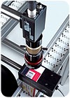
The integrator, with the help of the smart camera/software provider, should be able to provide the camera technology to produce good results for the system’s needs. Source: Edmund Optics
Cameras
After the illumination is worked out, attention should turn to the imaging device or camera that will be used in the system. There are a variety of camera resolutions, imager sizes and camera features available. This range of products only grows when one brings into account the intelligence of their associated algorithms.One of the biggest mistakes made in many systems is not having enough pixels on a given feature to yield accurate, reliable, repeatable results. Understanding where algorithms really maximize their capabilities relating to the application will go a long way toward yielding the desired results, not to mention allowing the operator to directly correlate how many pixels the imager needs.
For example, if there is an object with group of dark circles on a light background it is easy to count how many circles are in a given area even if it only has an area of 2 x 2 or 3 x 3 pixels on each circle. Each one will appear to be a dark spot on a bright background and easily analyzed by the software. Now extend the requirement a bit. Say the operator wants to measure the roundness of each circle. Even with the most powerful blob analysis, edge detection and sub-pixel algorithms employed, highly accurate and repeatable results are basically impossible.
By simply stepping up a level in camera resolution, the operator could increase the number of pixels being analyzed by a factor four and thus greatly leverage those powerful algorithms. This also is an example of making sure that the system spec is written correctly. Obviously counting the dots is much different than measuring them. Luckily the operator will not need to figure this all out on his own. The integrator, with the help of the smart camera/software provider, should be able to provide the camera technology to produce good results for the system’s needs.
After the imager is selected and the illumination is worked out, the operator is on the last part of the system that needs to be determined. While every part of the system is critical, choosing the wrong optical solution can make all other efforts wasted.
One of the most critical things to remember here is that even if two lenses appear to have the same specification, it does not mean that they are equivalent products. For example, four different lenses could all be listed as 25 millimeter lenses with the same mounting types, same angular field of view and same F# settings. One may have been designed for the security purposes, one for document processing, one for high-end photography and one truly for machine vision.
Using the example listed above, all probably would be satisfactory for counting the dots. When taken a step further for measuring the dots for roundness, one will probably find that the lens designed for machine vision will far outperform the others. Again, a well-written spec will lead to the best choice when it comes to producing the right amount of image quality for the specific application. The most reliable way to ensure this occurs for the application is for the operator and the integrator to consult an optical expert.
Learn more about vision integration online at www.visionsensorsmag.com.
sidebar: tech tips
- A well-written spec is essential when it comes to producing the right amount of image quality for the application.
- A high-priced system can quickly repay itself through higher throughputs, higher reliabilities, reduced customer returns, increased customer satisfaction, reduced reworks and reduced system downtime.
- Ensure that each area gets the time it deserves and that long-term support is sorted out both internally and externally.

Figure 1: Contrast is the difference in intensity between blacks and whites. For an image to appear well-defined, black details must appear black and white details must appear white. The greater the difference in intensity between a black and white line, the better the contrast. The human eye can see a contrast of as little as 1 to 2%. A typical limiting contrast of 10% is often used to define the resolution of a CCD imaging system. Source: Edmund Optics
Additional Factors
Other fundamental parameters need to be considered when choosing optics and tying entire systems together, such as field of view, working distance, depth of field, and resolution and contrast.- Field of view (FOV) is the viewable area of the object under inspection. In other words, this is the portion of the object that fills the camera’s sensor. The size of the camera sensor chosen can have dramatic effects on the FOV produced and should be accounted for when putting the system together.
- Working distance is the distance from the front of the lens to the object under inspection. The height of the object under inspection and the total track of the system can play a large role. Additionally the lighting that is required for the application can have a great effect on the working distance required for lens in the system. Some lighting solutions must be integrated between the optics and the object. These can take up significant space, but need to be accommodated.
- Depth of field (DOF) is the maximum object depth that can be maintained entirely in focus. The DOF is also the amount of object movement-in and out of focus-allowable while maintaining an acceptable focus.
- Resolution of a lens is the minimum feature size or detail of the object under inspection that can be reproduced by the lens; contrast is linked with resolution. Contrast describes how well the blacks can be distinguished from the whites.
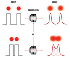
Figure 2: Contrast is not constant- it depends on frequency. The dots at the top of the figure can be imaged through a lens. They blur slightly. If the spots are moved closer, their blurs overlap and contrast decreases. When the spots are loose enough that the contrast becomes limiting, that spacing is the resolution. Source: Edmund Optics
This is intuitively obvious, but it is more important than it may first appear. The contrast is the separation in intensity between blacks and whites. Reproducing object contrast is as important as reproducing object detail, which is essentially resolution.
Let’s take the dot example one more time. If two different lenses can both resolve the spots but one can do it with a contrast of 10% and the other with a contrast of 50%, the lens with 50% is going to far out-perform the other.
Consider two dots placed close to each other and imaged through a lens. Because of the nature of light, even a perfectly designed and manufactured lens cannot accurately reproduce an object’s detail and contrast. Even when the lens is operating at the diffraction limit, the edges of the dots will be blurred in the image. When they are far apart-in other words, at a low frequency-the dots are distinct, but as they approach each other, the blurs overlap until the dots can no longer be distinguished. The resolution depends on the imaging system’s ability to detect the space between the dots. Therefore, the resolution of the system depends on the blur caused by diffraction and other optical errors, the dot spacing, and the system’s ability to detect contrast.
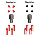
Figure 3: Distortion (%) = Actual Distance (AD) - Predicted Distance (PD) x 100 Predicted Distance (PD)
Using measurement software and a dot target of known size, one can measure the distortion at different distances from the center of the image. Source: Edmund Optics
Using measurement software and a dot target of known size, one can measure the distortion at different distances from the center of the image. Source: Edmund Optics
There are other things that can be done to enhance a lens’s performance within the system. If using only one color, then chromatic aberration is no longer an issue. If the system does not need to be color-corrected over the entire spectrum, the lens design can be simpler. Going monochromatic may also simplify the illumination system since monochromatic LEDs use less power and create less heat than white light incandescent bulbs. This effect also can be achieved by using color filters with a white light source. Filters can be a low cost way of improving the system’s capabilities. Additionally, monochromatic light sources and filters can be used to perform color analysis.
Distortion is a geometric optical error (aberration) in which information about the object is misplaced in the image, but not actually lost. Distortion can come in a couple of different forms.
There is monotonic distortion, which means that the distortion is consistently positive or negative from the center of the image out to the edges. Distortion that is not monotonic will actually go back and forth between negative and positive distortion as the operator works his way from the middle of the field to the edges.
Distortion that is not monotonic can occur during the design of the lens to reduce overall distortion in the lens or from factors specifically related to the design type. Whether the distortion is monotonic or not, software can be used to factor out the distortion so that accurate measurements can be made of the image.
Using measurement software and a dot target of known size, one can measure the distortion at different distances from the center of the image. Distortion is not linearly correlated to the distance from the center of the field, and this is true for monotonic and nonmonotonic designs. After this is done, distortion can either be processed out of the image or taken into account during measurement. Removing distortion from an image and redrawing the image can be a processor intensive operation.

Figure 4: Non-telecentric, Telecentric Imaging results at the image plane of a telecentric and non-telecentric lens system. Notice the telecentric system eliminates perspective distortion. Source: Edmund Optics
Telecentricity
Perspective errors, also called parallax, are part of everyday human experience. In fact, parallax is what allows the brain to interpret the 3-D world. Humans expect closer objects to appear relatively larger than those placed farther away. This phenomenon also is present in conventional imaging systems in which the magnification of an object changes with its distance from the lens. Telecentric lenses optically correct for this occurrence so that objects remain the same perceived size independent of their distance, over a range defined by the lens.For many applications, telecentricity is desirable because it provides nearly constant magnification over a range of working distances, virtually eliminating perspective angle error. This means that object movement does not affect image magnification. Thus the accuracy and repeatability of systems are greatly increased.
In a system with object space telecentricity, movement of the object toward or away from the lens will not result in the image getting bigger or smaller, and an object which has depth or extent along the optical axis will not appear as if it is tilted. For example, a cylindrical object whose cylindrical axis is parallel to the optical axis will appear to be circular in the image plane of a telecentric lens. In a non-telecentric lens this same object will look like the Leaning Tower of Pisa; the top of the object will appear to be elliptical, not circular, and the sidewalls will be visible.
After the operator has correctly matched the optics to the selected camera and the lighting capabilities have been maximized, thus giving the software algorithms the best images to analysis, the system is ready for testing and then complete deployment.
At this point one will need to cover all of those items needed to build a system that will stand the test of time. This will include building enclosures to resist the potentially hazardous environments associated with the factory floor, eliminating unwanted ambient lighting conditions and most importantly, benchmarking the system.
The operator will be spending a bit of money to get the system up and running and each part of the system has an equal load to bear. Be sure that each area gets the time it deserves and that long term support is sorted out both internally and externally in order maximize ROI for the long term.
Looking for a reprint of this article?
From high-res PDFs to custom plaques, order your copy today!


